Fusion 360 Woodworking: Dovetail Joints – Watch the Free Tutorial!
Demo File – Dovetail Joints
- Open the Fusion 360 file via this link – https://a360.co/3kmguR2 (see note below!!)
- Note: The hub will say the file is empty – don’t worry! This is because the parameters are the only thing in the file and Fusion 360 says this error message in the web browser preview if there are no solid bodies.
- Click the blue “Open in Fusion 360” button. Wait about a minute and you should be prompted by your Browser if you want to open it with the Fusion 360 Desktop App.
- Click Open.
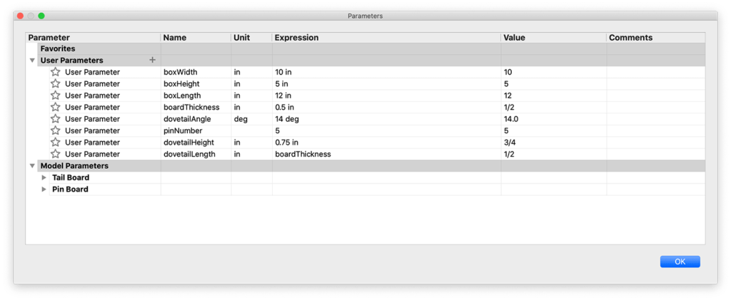
Parameters for Dovetail Joints

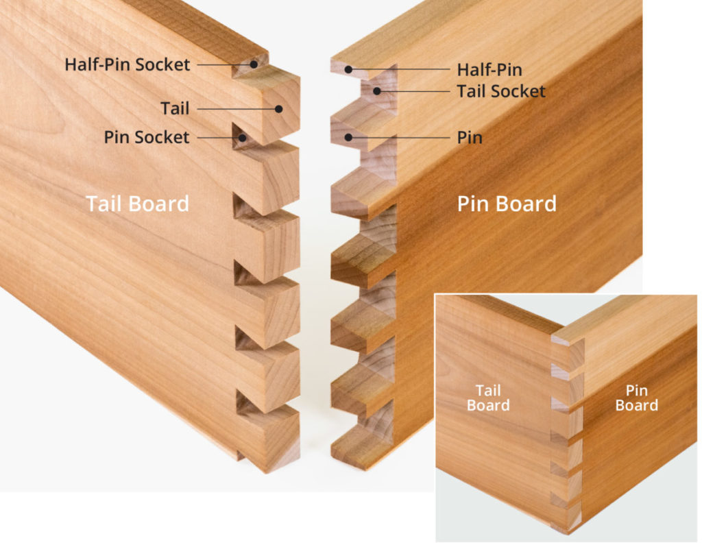
Dovetail Joint Terminology

Save Time and Master Fusion 360 for Your Woodworking Projects
Quickly learn the correct techniques with our structured and easy-to-follow Fusion 360 courses for woodworking. Learn Fusion 360’s core workflows, best practices, and professional tricks with our Masterclass: Fusion 360 for Professional and Hobbyist Woodworkers.

Transcript
There are two main ways to create parametric dovetail joints in Fusion 360, but one way is better than the other.
We’ll also take a look at the best way to apply Joints to make sure we drive the parameters without breaking the file.
If you know an easier or better way then share them by commenting below as you watch the tutorial.
I’ve gone ahead and created Users Parameters that we’ll use as we set up the sketches. To save time you can grab my demo file with the parameters already set up. Check out the link below in the video description.
To start, we’ll create a new component for the Tail Board. This will help us manage the assets as we copy the boards.
Our initial board will be created with a simple 2-point rectangle. I like to use the shortcuts box, which is activated with the keyboard shortcut letter “S,” as in Sierra. We can then simply search for the feature we’re looking for, or in our case, the 2-point rectangle.
Once we select it to activate it we can select the front origin plane. I’m selecting this plane as we’re going to start with the front board of this box.
We’ll follow the best practice of starting the sketch at the origin point. After clicking the origin, we can drag the mouse out and type out the user parameter of boxHeight for the height, and boxWidth for the width. If you need to toggle between inputs you can simply hit the tab key.
We can then click to place the rectangle.
Let’s toggle open the Sketches folder in the Browser. You’ll notice the lock icon, which signifies we have a fully-defined sketch. This is critical in making sure our model is parametric and predictable.
We also want to keep our sketches as simple as possible. If you can, you always want to place objects in separate sketches.
Let’s flip to the Solid tab and activate the Extrude command. We’ll then extrude this out to the boardThickness parameter.
Before we forget, let’s also rename the sketch in the Browser. Click once to select it and a second time to edit the field… and we can type out “Board”.
We can now sketch on the front face of this board to make the tail shape of the dovetail. Again, we’re separating these sketches so we keep them as simple as possible, making them easier to fully-define. This will also make sure we can update the design in a predictable way.
Right-clicking on the front face, I’ll select “Create Sketch”.
To create the tails we’re going to sketch the negative space where the pins will slide in. We’re only going to sketch the center one, and we’ll use the modeling tools to pattern it – again allowing us to keep our sketch simple.
Before we sketch, you’ll want to head up to your profile picture or initials, and select the user preferences. Under the Design tab, you’ll want to turn on “Auto Project Edges on Reference”.
This setting will ensure we can snap to the existing 3D edge and will let us sketch in the middle of the object, while still fully-defining our sketch.
Back in our sketch, we can activate the line tool with the shortcut letter “L,” as in Lima.
Let’s also turn the construction option on in the Sketch Palette, since this first line will serve as our symmetry line.
Once we find the midpoint constraint or triangle icon, we’ll click to snap the line in place. The length of this line will be set to our dovetailLength parameter.
We also want to snap this in place by clicking when we see the perpendicular icon in the corner, leaving us with the perpendicular constraint.
Now that we have a centerline we can sketch out the shape on both sides…but we’ll only dimension the one side. We’ll then use constraints to fully-define this sketch.
We can turn off the construction option and create a line running straight up. I’ll set this to the dovetailHeight parameter divided by 2 since we’re only creating half.
We also want to place this 90 degrees to the previous line.
Next, we need to create our angled line so we get the dovetail shape. We don’t know the length of this and always want it to be driven by the dovetail angle, so we can hit the tab key to switch to the degree field.
Plugging in the dovetailAngle parameter leaves us in the wrong direction.
To fix this we can take 90 degrees, for a line that would be straight out and we’ll subtract the dovetailAngle. We can then click on the edge of the board, where it snaps into place…again because we have that Auto Project Edges on Reference turned on.
Our sketch should be fully-defined at this point, but we need to create the opposite side.
Let’s hit the escape key to clear all commands.
I’m first going to click and drag on these dimensions, to get them out of the way.
With the line tool, we’ll want to create the same shape on the other side of our centerline. However, this time we won’t add dimensions. We’ll use the symmetry constraint to force these lines to be the same.
Remember we always want to minimize the use of dimensions and use constraints when possible.
After activating the symmetry constraint in the toolbar, we’re able to select both lines, followed by the centerline. Notice how that forces it to be the same.
We’ll want to do this to the second line as well.
Our sketch should once again be fully-defined.
Let’s rename the sketch to keep our file nice and organized.
Fusion 360 will automatically leave the sketch environment if we activate a modeling tool, so we don’t need to finish the sketch.
Let’s instead hit the keyboard shortcut letter “E,” as in Echo, followed by selecting the sketch profile.
We want this profile to be cut out of the board so we’ll use the boardThickness parameter with the negative sign in front of it.
Right now we have two simple sketches and one 3D body. The key takeaway here is that you could technically pattern the sketch using the sketch pattern tool. However, when possible, you always want to pattern 3D bodies, features, or components over sketches.
That’s actually where most people go wrong. They want to pattern the sketch, making it complex and more likely to break.
Using the modeling pattern feature helps us keep the sketches super simple and lowers our chances of breaking something when we plug in different parameters.
Before we pattern this cutout, we’re going to mirror it to the other side of our board. This will make our mirror feature simpler, putting the ‘heavy lifting’ on the pattern command, which generally performs better.
Let’s first create a midplane construction plane to serve as the mirror plane.
We can select each end of the board and click OK.
With the modeling mirror command, we’ll change the mirror type to Features, which allows us to select the Extrude object in the timeline..
Our mirror plane will be the midplane that we just created.
Once that is complete we can also right-click on the plane and find the option to hide it.
Now that we have a cutout on each side we can activate the Rectangular Pattern feature in the toolbar.
The pattern type should also be set to Features, which lets us select the last Extrude, as well as our Mirror feature.
For the direction, I’ll select the edge of the board.
Before we fill out the quantity we’ll need to set the Direction Type to Symmetric… that way our pattern runs in both directions.
We can then plug in our pinNumber parameter into the quantity option. This will dictate how many dovetail pins the adjoining board has.
If you look at standard dovetails you’ll find there are usually half-pins on the outside. With this in mind, we’ll want to set our distance so this pattern ends up with the last cutout being only half the shape.
Our boxHeight parameter is currently set to 5 inches, so I’m going to set the distance to boxHeight divided by 2, which should correctly space out the 5 pins.
The good news is that we’ve now done the hard part!
Making the board with the pins will be even easier as we can quickly reference the existing geometry.
Let’s first create a new component for the Pin Board.
Again, we’ll start with a 2-point rectangle from the origin point of the front origin plane.
We’ll need the BoxHeight parameter and the boardThickness parameter.
With the Extrude command, we can make this run back the distance of the boxLength parameter.
Before we use a feature to cut out the shapes on this board, we’ll want to copy the two boards to make the rest of the box. That way we can maximize how the cut out is computed.
Let’s first ground one of these existing boards by right-clicking on it in the Browser, followed by the ground option. This will freeze or lock the board in place so we can apply joints to the remaining boards.
We can then apply a rigid as-built joint since the other board is already in the correct place.
To create the other two boards we’ll want to copy them in the Browser. I’ll copy the Pin Board first, making sure that we use the Paste New function, which will keep it independent from the original. This is crucial as we don’t want them to inherit the pin cutout.
We’ll also want to click OK to place it and we can hide the original component in the Browser. That will let us use the Joint command to position the board.
To join this first board we’ll select the middle area since our middle cutout will never change. We can also use the CMD key on Mac or Alt key on Windows, to lock in to the face, making it easier to select the joint origin.
Selecting the Joint origin on the other side will place this board close to the position. Again, the goal is to make sure our board is joined here no matter what our parameters change to.
We’ll have to follow this same process for the Tail board.
This time I’ll use the top inside edge.
You’ll see that we may have to once again flip the joint origin by hitting the flip button.
With all of our components turned back on, we should now have four boards that are joined together and can only be altered by our parameters.
We need to cut out the negative space for the tails.
With the use of the Combine command from the toolbar, we can select the left sideboard as the Target Body and the front and back boards as the Tool Bodies. Of course, we also want to cut this object out, so be sure to change the operation to cut.
Check the Keep Tools option as well, as that will ensure our front and back boards still exist after the operation.
Notice how clear the dovetail on the left is compared to the one on the right.
We can also check that things are cut out properly by hiding the other components
Repeating the Combine command we can do the same process for the right side. Remember, we want to use both Tail Boards as our cutting tools.
Our dovetail joints are now complete and we can test the User Parameters.
Perhaps we want our pins to be smaller. We can simply change the dovetailHeight to a half-inch instead of three quarters.
We could also change our degree from 14 to 17 degrees.
We can also change the width or length of our box, and the boards should remain joined together.
Utilizing these parameters can help us explore dovetail styles or dimensions before trying them in real-life.
To summarize this video, make sure you keep sketches as simple as possible, and when possible use the modeling commands over sketches.
Thanks to all the new Patrons who joined in the last two weeks…
Corinne, Phil, Josh, Tom, both Michael’s, Gary, Hannes, Jo, Chamberlain, Chris, Antoine, and Bill.
And thank those who supported the channel via my Buy Me a Coffee page…
Clem, Joseph, and the anonymous contributor.
I appreciate all of your support as this helps me continue to invest in my equipment to make more tutorials even better.
Be sure to hit the like button if you learned something in this video! Then, click on that playlist in the lower right-hand corner to watch more woodworking tutorials.
Hi Kevin,
first of all I made a metric version of your dovetail parameters.
I added the parameter “dovetailWidth” to have more design possibilities.
The parameter “glueGap” is not implemented at the moment.
Your setup in the video it is only possible to have an odd number of pins. Because you start in the middle of the tail board. When you start with a half tail at the edge of the board, you can set the pin number to even and odd values.
The rest is the same in your video.
If you like, I can send you my F360 file. I also added a demo section for 3D printing.
As I have a Shaper Origin, this is a very nice tool to create dovetail templates for cutting. I would like to publish this file on Shaper Hub and mention you and your video, if you like.
CU
Jens
Hi Jens,
Sure thing! I’d love to check out the file. You can share the Public Link as a reply to this thread.
Feel free to post it on the Shaper Hub. I have an Origin as well…so that would be a cool project to try 🙂
Cheers,
Kevin
Hi Kevin,
let’s hope it is working:
https://a360.co/3ge0G0w
I will wait for your comments before I post it on Shaper Hub or Shaper Community.
CU
Jens
Hi Jens,
Thanks for sharing the link! Was I just supposed to look at the body/component that is visible? I tested its parameters and overall it seemed to adapt well…but it did cause some warnings and errors in the timeline. I’m not sure if those were related to the other components or which is supposed to be included?
Cheers,
Kevin
Hi Kevin,
you are right!
The file still needs to be cleaned up 😉
Your original design is also included (only changed the parameters to metric values). When the number of pins is even, it may produce some warnings and of course a weird screen output.
At the moment I am quite busy, so it may take some time before I continue my work on this file.
Maybe you would like to include it in your tutorial.
CU
Jens
No worries! Thanks for the update. I just wanted to confirm that I was looking at the right thing. I know sometimes others share files but forget to save the latest version. I’ve spent time ‘insepcting’ others files only to find out it wasn’t the right file 😉
I like your approach and think it works well for having both an odd/even number of dovetails. Like many thing in Fusion 360, I think there are pros and cons to each approach. It’s definitely worth sharing though.
Cheers,
Kevin
Hi Kevin,
I just put the following project onto ShaperHub:
https://hub.shapertools.com/creators/5e760505c8f2b1000fb45e01/shares/5f3916d3fe9a3e0011b1ce87
It has the cleaned up version of the dovetail template. The next Thursday there will be a Live Session with the topic “Cutting dovetail joints” from the German Shaper Team. I just sent them message, so they might use/show the template generator…
CU
Jens
Hi Jens,
Thanks for sharing the link! I’m glad to see you got it published.
I’ll have to keep an eye out for the live session… Shaper has been doing so many live streams lately I haven’t been able to keep up 🙂
Cheers,
Kevin
Hi Kevin,
the german Shaper Session about dovetail cutting just aired.
https://www.youtube.com/watch?v=_lC8Xebtdbk&feature=youtu.be
The “Template Generator” was mentioned several times.
I will try to add the passes for the cutter (like shown in the video).
I hope you get some new subcribers for your YT channel.
CU
Jens
Perfect. Thanks for the update, Jens. I’ll check it out! 🙂
Hi Jens,
any progress in adding the passes for the cutter?
Looking forward to.
Many thanks
Jochen
hi thanks for video Kevin. can u suggest how to cam this with boards being flat on table?
Hi Jim,
With CAM/CNC, it’s usually best to mill the boards vertically. Here’s a good example – https://youtu.be/0KVqrmXqHTM
That allows you to use a dovetail bit, which often provides clean results.
If you want to do it with the wood boards laying flat, you could do it with a standard endmill bit and the ‘3D adaptive stepdown’ toolpath. You’ll want to make sure to go into the spoil board to ensure the cut is all the way through.
Cheers,
Kevin