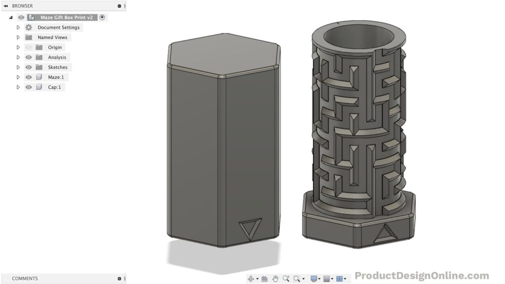
Learn how to design your very own custom puzzle box in Fusion 360. These labyrinth style maze boxes make for great gifts. Don’t just give cash or a gift card – make them earn it!

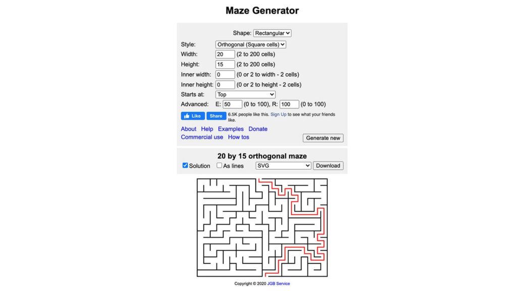
Online Maze Generator
I mention this online Maze Generator in the tutorial. You can use it or another online generator – there are plenty to choose from! You can also manually create the maze by sketching in Fusion 360.
If you decide to use a generator then make sure you’re able to download the file as an SVG extension. Scalable Graphics Files (SVG) will ensure we can scale the file without it getting distorted. We can also insert SVGs into Fusion 360, which automatically converts them to sketch geometry.
Important: Please read the licensing if you use an online maze generator. Many of them do not allow the sale of products or commercial use with the maze unless you purchase a commercial license.

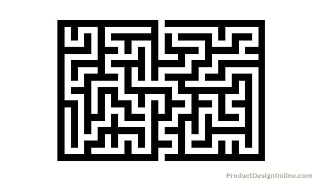
You will likely have to thicken the stroke weight if you use an online maze generator. This can be done with any graphics program, including Adobe Illustrator and Inkscape. You could also use a free online graphics program.
Adobe Illustrator is my preferred graphics program, so I’ve outlined the steps below. The process should be the same in other programs, but they may use different terminology.
Thicken an SVG Maze in Adobe Illustrator
- Open the maze SVG file > Select everything
- Window > Stroke > Change stroke to 3mm.
- Scale Artboard so the entire maze fits. The increased stroke may have put it over the edges.
- Object > Expand > Make sure Fill and Stroke are checked. Click OK.
- Pathfinder > Unite. That will make sure everything is one shape, which ensures we have minimal geometry when brought into Fusion 360.
- Save the SVG and use the “Insert SVG” command within Fusion 360.
My Demo Maze

I ended up creating this maze on my own in Adobe Illustrator. You can follow along by downloading the Maze.
Print Settings
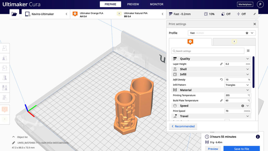
I used Ultimaker’s Cura to slice this model. You can use the default Fast printer profile. To cut down on print time I changed the infill to 10%.
Estimated Print Time: 3 Hours 55 Minutes
Layer Height: .2mm
Shell – wall thickness: 0.8mm
Shell – wall line count: 3
Infill Density: 10%
Support: No

Transcript
Design your custom maze puzzle box in Fusion 360
Up until two weeks ago, it was nearly impossible to create something like this maze puzzle box in Fusion 360.
While other creators were sharing their excitement about finally being able to wrap text… I realized the new emboss feature opens up way more opportunity than that. We can now easily wrap sketches, SVGs, and other designs around curved surfaces.
Let’s take a look at how to create your very own maze puzzle box.
Also, just a quick heads up this tutorial assumes you have a basic working knowledge of Fusion. That will help keep the focus on the project and the emboss tool.
To start, we’ll create a new component for each part. The first one will be for the maze and the second one will be for the cap.
With the Maze component active, we’ll create a new sketch on the bottom origin plane.
We’re going to create a cylinder that we’ll use to wrap the maze around.
With the center-circle command, I’ll start at the origin point, and I’ll make the diameter 30mm. A lot of the size is up to you, but I’ll discuss some key dimensions in a minute.
I’m going to Extrude the circle at a distance of 70mm.
Before creating the maze, we’ll want to shell the cylinder, making it hollow. If we try to do it later the shell command will mess up the maze.
With the Shell command active, I’ll select the top of the cylinder, and I’ll define the thickness as 2.4mm. Again, this dimension can be whatever you desire. I’m using 2.4mm as that’s easily divisible by my wall line thickness that I have set in Cura.
The last thing we want to do is create an offset construction plane. This is to ensure our sketch is in front of the surface. We’ll select the front XZ origin plane and all that matters is that it’s placed in front of our cylinder. We’ll use this construction plane for our Maze sketch.
We can then right-click on the plane and create a sketch.
With the Emboss command, you’ll find that bodies cannot intersect with one another. Otherwise, you’ll get an error and Fusion won’t compute it.
To help avoid this, we can create a construction rectangle, which we’ll use as a reference.
I’ll activate the 2 point rectangle. We’ll set the height to the same as the cylinder, or in my case 70mm. For the width, we want this to be the circumference of the cylinder.
The great thing about Fusion 360 is that we can type functions within the dimension inputs.
If you recall we defined the diameter as 30mm. For our equation, we can use the radius of 15mm or half of the diameter.
Our circumference is 2, times with the asterisk symbol, then what most don’t know is you can use PI by simply typing the capital letters P and I. Then, we need to multiply that by our radius of 15. That will give us the circumference of the cylinder.
Before clicking to place the rectangle let’s hit the construction option in the Sketch Palette.
We’ve now defined the max area we can use to sketch. Anything outside this box will not be able to wrap around the cylinder.
At this point, we have a choice to make. One option would be to use Fusion 360’s native sketch geometry to manually sketch out the entire maze. It’s certainly possible, but it’s likely going to take a fair amount of time.
Instead, I found this online maze generator. Just be sure to read their licensing, as this cannot be used for commercial use without buying a license. A link to this and everything else mentioned can be found on this tutorials resource page.
You’ll have to adjust the size based on how large you’re making your model, keeping in mind that we can also scale it in Fusion 360.
The cool thing about this generator is that we can check the solution option. This lets us hit generate, and we can preview the maze. You can then continue to generate options until you find a maze that you like. This allows us to choose how hard the puzzle box is to open.
Lastly, we have to get this into Fusion 360, so we’ll use the SVG option. SVG stands for “scalable vector graphic.” In short, it’s a common graphic file extension and Fusion 360 can recognize it and turn it into native sketch geometry.
The only problem is that we need to thicken the maze lines so they’re wide enough to Extrude. Now you could do this by offsetting each line in Fusion 360, but again that’s going to take a fair amount of time.
Instead, I opened the SVG in Adobe Illustrator and simply changed the stroke weight. I then expanded the paths and used the unite option to join them together.
To be clear, you don’t need Illustrator. This can be done with Inkscape, or any other graphics program, including several free web-based programs.
As always, you can also follow along by downloading my file from the resource page.
Back in Fusion 360, we can go to the Insert dropdown and we’ll activate the Insert SVG option.
We’ll select the SVG from our local computer.
At this point, we can scale the SVG making sure it fits within our box. I’m going to intentionally make it larger than the box to show you what happens.
I’ll activate the Emboss command from the create dropdown of the Solid tab.
With Emboss, we need to select all the sketch profiles and then we can select the cylinder for the faces.
You’ll see that I get an error message. Again, this is because Fusion can’t compute the bodies if they self-intersect.
I’m going to undo, so I can re-insert the SVG.
This time I’ll scale the SVG to 1.433. This is simply the largest number I found this would scale to, while still fitting within the box.
Another thing I learned experimenting with the Emboss feature is that you have to be careful when you’re close to the top or bottom edge of a body. If you’re too close to an edge Fusion may give you an error because it doesn’t know where to place the sketch. To avoid this, I’m going to move the SVG to the middle.
I’ll move it up 3mm and click OK.
Once again I’ll activate the Emboss feature and I’ll select both profiles. This time as I select the face you’ll see that it wraps nicely around the cylinder.
We no longer have to do the time-consuming workaround with the sheet metal tools.
The amazing thing about this new feature is that we can adjust the position of the emboss without having to move or edit the sketch. We can move the position with the arrows or the dialog.
We can also switch this to a deboss by selecting that in the dialog. Notice how it cuts into the cylinder.
Let’s leave this set to emboss at a distance of 2mm and click OK.
Look at how easy that was to wrap this maze around the cylinder.
At this point, we need to add chamfers to all of the edges, ensuring they can be 3D printed.
Let’s first clean up the top. With the Extrude command, we can select the inner profile. Using the “To Object” Extent type we can select the outer face. This will cut away the excess, leaving us with a flush surface.
With the Chamfer command, we’ll have to select all the outer edges that make up the maze. You can use selection filters to help with the selection. For the sake of time, I’m going to skip ahead to where they’re all selected.
Within the Chamfer dialog, we’ll want to set the Chamfer Type to “Distance and Angle”.
You’ll want to set the degree to 45 degrees, which leaves us with a nice overhang that can print without supports. For the distance, you’ll want to set this to 1.5mm or whatever aligns with your Extrude distance.
Once that is complete we can proceed by making the base of this Maze part. We’ll then create the cap that has a notch on it.
I’ll create a new sketch on the bottom face. You can create any base shape you’d like, but I recommend a polygon, which makes it easier to hold and twist.
I’ll sketch a Circumscribed Polygon with a radius of 20mm. At the very end of this project, we’re going to put an indicator near the opening. That will make it easier to understand where the notch is and where the maze ends.
To have a surface area for the indicator, we’ll want to rotate the polygon. We can shift-click a vertex and the center point before adding a horizontal constraint. This will ensure our flat surface area aligns with the cutout.
With the solid Extrude command, we can extrude this in two directions. This will allow us to go to the bottom surface, using the “To Object” Extent Type.
I want my base to be about 10mm thick, so I’ll then go 7mm in the other direction while making sure this body joins the existing body. Just be sure to select the inner circle profile as well as the outer polygon.
Once that is complete, we’re ready to work on the cap. We’ll add fillets at the very end.
Let’s go ahead and activate the Cap component.
We need to copy over our base shape, so we can use that as the foundation of our cap. Let’s use the Project command to project the edges of the top face.
This leads us to the most critical point. We need to factor in clearance so the cap will fit over the maze portion.
The cap should only have the notch at one spot, so we cannot offset the existing geometry. Instead, I’ll draw a new center circle and I’ll place it larger than the projected circle.
That will allow us to dimension the distance between the two, which we’ll set as our clearance. I did several test prints and found .5mm to be the perfect clearance for this maze box.
Of course, you may have to tweak this based on your print settings and printer’s tolerances.
We can now Extrude this up to the top of the Maze component, once again using the “To Object” extent type.
We can also change the Start option to “From Object” which will allow us to define an offset distance of .5mm, factoring in a small clearance at the bottom.
Let’s create a new sketch on the top face, and we can Extrude both the outer and inner portion, finishing off the top. I made mine a thickness of 2mm.
We’re now ready for the most important part. We have to create a notch within the cap which forces the user to navigate the maze.
We need to locate the opening at the bottom of the maze, as we want the notch to be positioned here when the cap is fully closed.
There are several ways that you could do this, but I’m going to sketch on the bottom of the cap, and we’ll simply offset the notch to the correct position.
We need to sketch out a triangle with a minimum clearance of .4mm. We also have to make sure it’s not too small or the notch will simply slide over top the maze.
I’m going to start with a construction line in the middle. Because I have the Auto-Protect feature on in my preferences, you’ll see it projects the curved edge.
With the line tool, I’ll simply sketch out half of the triangle shape and we can dimension it afterward.
We’ll have to create a sketch point to reference with the dimension. That will allow us to dimension from the point to the bottom line, where we can use the .4mm clearance.
We want the triangle to mimic our chamfered edges, so I’ll add a degree dimension of 140 degrees between these two lines. To follow the best practice of fully defining sketches I’ll add the remaining dimensions. The bottom line will be .5mm, the angled line 4mm and the top line can be whatever it defaults to.
We can then mirror this over to the other side using the Sketch mirror command.
Hiding the Maze component will allow us to select these two profiles with the Extrude command.
The position is really important, so we’ll need to look at Maze. For now, let’s Extrude this to a distance of 5mm and click OK.
We’ll want to lower the Cap opacity to 50%, which will let us see how things are positioned. I want the notch to line up with the first maze area, and to be away from the edge a bit, so I’ll edit the Extrude. We can then change the start type and set the offset to -2.5mm. You may have to adjust this according to your maze pattern.
Once that is complete, we can hide the Maze component.
We’ll use the Chamfer tool to ensure the edges don’t run into the maze walls.
Again, we’ll want to set the degree to 45 degrees, ensuring this will print well. We can then define the distance as 1.5mm.
All that matters is that this fits within the chamfered shape of the maze. We can turn the Maze component back on and double-check. Since that looks good, I’ll turn the opacity back to 100%.
There are two last things we’ll do to finish off the model. Let’s first fillet all the outer edges so they’re not sharp, and then we’ll create an arrow indicator for the notch.
With the top component active, I’ll fillet all the vertical edges to 3mm.
We can then add a new selection and select all the top and bottom edges. Using the faces will help us select everything quicker. For these edges I’ll add a small fillet of 1mm, ensuring they’re not sharp.
You may have to hide the components to select areas where the two parts come together. We want to avoid selecting any of the maze or inner workings.
With the cap on, there’s no easy way to see where the notch is, so let’s activate the component and create a new sketch on the front face.
This is where you can get creative and put any shape or indicator. I’m simply going to create a 5 x 6mm triangle and Extrude cut it away at 1mm.
I’ve repeated the same on the other side and added a 1mm chamfer to ensure this prints well.
The last thing I recommend is to use the Interference command. This will help you double-check that the cap body doesn’t collide with the Maze body.
If that’s clear, then you’re ready to print them out. Simply right-click on the components to save them as STL files and send them to your chosen Slicing software.
Thanks for watching this tutorial. I also wanna give a quick shoutout to all the new Patrons and other supporters from the last two weeks. If you’ve learned from my tutorials then consider joining my Patreon. That helps me continue to invest in camera equipment to better the tutorials even further.
Last but not least, subscribe if you haven’t already and then watch some more tutorials on 3D printable projects.

SVG files are text files. The ones from http://www.mazegenerator.net/ are easy to edit. Open the file in Notepad. Change the stroke-width parameter to 7. Save the file.
Hi Ron,
Great tip – I’ve edited SVGs that way before…I don’t know how I overlooked that. Thanks for sharing this with everyone!
Cheers,
Kevin
When I edit the svg by text editor or with inkscape, it still imports to Fusion as a single thin line rather than the thickened lines. Is there a setting in Fusion that I might have wrong?
Hi Travis,
With Inkscape, you’ll need to do the “Stoke to Path” option as outlined below.
I believe the edit of the SVG as a text file per Ron’s comment above does not actually work because the paths are not “outlined” like they will be coming from a graphics program (following the right steps, of course).
Cheers,
Kevin
First of all, thank you for your great tutorials. This would make for a great gift-box. Being able to create different mazes for different boxes. However, as I have no experience in using vector applications, I’m struggling to get the maze correct in Inkscape before importing it to Fusion 360.
Trying to sort out the terminology at https://wiki.inkscape.org/wiki/index.php/Inkscape_for_Adobe_Illustrator_users#Pathfinder I’m still not able to get a correct looking maze out of Inkscape. Even though your steps in Illustrator are few and quick, I’m having trouble translating it to Inkscape. Do you have time for a quick explanation on how you would do the Expand option @5:28 in the video if you were to use Inkscape. Thank you in advance.
Hi Bjørn,
Thanks! Glad to hear you’re enjoying the tutorials!
You’re correct that Inkscape does not have an ‘Expand’ option. What you can use instead is the “Stroke to Path” operation.
1. Import your Maze SVG file, which will be a single stroke.
2. Resize as appropriate. Hold down the CTRL key to lock in the aspect ratio.
3. Make sure the entire maze is selected > Object > Fill and Stroke > change the stroke width to desired thickness.
4. With maze still selected, Path > Stroke to Path. This will make each ‘segment’ of the maze an individual component (or piece).
5. You will need to combine each individual piece. Double-click on one segment, then select CMD+A (Mac) or CTRL + A (Windows) to select all individual objects. Object > Combine. This will combine it into 1 shape.
6. You can then “Save As” an SVG (either Plane SVG or Inkscape SVG will work).
Cheers,
Kevin
What are the steps for creating the triangle indicators because in the video it doesn’t show the steps
Hi Jaylen,
Please see approximately 18:00 minutes in the video. There is a YouTube chapter as well. The triangle indicators are specifically called out there.
Cheers,
Kevin