Making CAD education accessible to anyone, anywhere.
We hope you’ve been enjoying the wealth of free Fusion training provided by Product Design Online. Our commitment to empowering individuals like you with valuable skills is at the core of what we do.
If you’ve found our free content beneficial in your learning journey, we kindly ask for your support through a donation. Your contribution will not only help sustain the availability of free materials but also enable us to expand our offerings and reach even more learners globally.
Please select a donation method
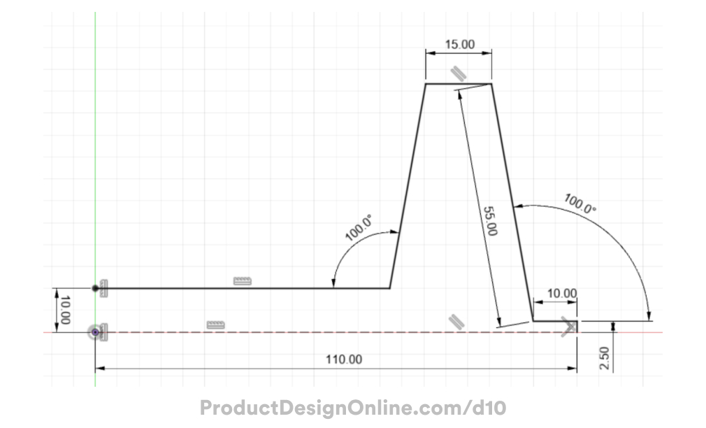
Sketch Dimensions
Use the following sketch dimensions to create the sketch profile for the dog bowl. This image does not need to be inserted into Fusion 360 and is provided so you can look at the dimensions without pausing the video.

Transcript
Welcome to Day #11 of Learn Fusion 360 in 30 Days. I’m Kevin Kennedy,
and today we’ll create a dog bowl while looking at some beginner surface modeling concepts, including offsetting and thickening surfaces. We’ll also look at the Section Analysis tool.
We’ll start by sketching half the dog bowl shape, as we’re going to use the Revolve tool to create the full shape.
Activate the Line tool, and start sketching on the front origin plane.
Starting at the origin point, we’ll head to the right 110mm. The next line will be our thickness of 2.5mm.
Go to the left 10mm.
For the next line, we’ll define the angle as 100 degrees, with a length of 55mm. Remember, you can press the Tab key at any time to switch between input fields. This allows you to define the angle first, which is sometimes helpful.
Next, 15mm to the left.
The last two lines, we don’t know the length of, so we’re going to go past the length on purpose, and we’ll trim away the excess.
Clear out the Line command with Escape, then reactivate it so we can start from the left side.
Make this line run past the previous line.
We’re also going to add a 10mm sketch dimension between the two horizontal lines.
Notice our sketch is not yet fully defined, as we have blue sketch geometry. We’ll need to add another 100-degree dimension between these angles.
Using the sketch Trim tool, we can select the excess line segments to get rid of them.
We’ll also need to add a vertical constraint to the end point of our line and the origin point. This ensures that our endpoint cannot move around.
Our sketch is now fully defined, and we can double-check by finding the red lock icon.
Surface modeling does not require a fully closed sketch profile like Solid modeling. That means we do not need to close off the left opening. This is one concept that makes surface modeling different from solid modeling. Generally, you can use less sketch geometry to accomplish things.
We’ll also want to turn the bottom line into a construction line as we’re not going to need that in our surface body.
This completes our sketch and we’re now ready to Revolve the sketch.
In the toolbar, we’ll head to the Surface tab, which houses all of the surface modeling tools. Surfaces are noted with the orange color, while Solid modeling tools are blue. Be sure to activate the orange Revolve tool.
Again, notice the Surface commands let us leverage sketches that are not fully closed profiles.
For the axis, we’ll select the center Z axis.
After clicking OK, notice we have an Orange revolve icon in the parametric timeline. We also have an orange surface body icon in our Fusion 360 Browser. Surface bodies are infinitely thin, meaning they have no real thickness to them until we define a thickness.
Before we define a thickness, we’ll want to add some fillets to the sharp edges.
Activate the regular Fillet command which works across solid and surface bodies.
Add a 5mm fillet to the top two edges and our lower inside edge.
Let’s also add a new selection set and define the bottom inner edge with a 2.5mm Fillet.
If we flip the model upside down, you can see that the inside is yellow. This simply helps us distinguish surface bodies from solid bodies. Surfaces will have one gray face and one yellow face if no appearance is applied.
You will also see that the surface body in the Browser lets us know how many individual faces make up the body. In our case, we have 10 faces after adding our Fillets. Without the Fillets, we have only 6 faces.
In its current state, the file could not be used for exporting or manufacturing, as there is no defined thickness. We’ll need to activate the Thicken command to define the thickness of the surface.
Notice ‘chain selection’ is on by default. This helps us select all 10 faces with a single click of the mouse. If we uncheck this, we could individually select faces as needed.
Let’s leave this checked and select the group of surfaces.
Define the thickness as 2.5mm. We want the Thickness to go in the inner direction, so we’ll add the minus symbol.
Watch what happens in the Fusion 360 Browser as I select OK. You’ll see that Thickening the surface body results in a Solid BREP body. However, Fusion 360 also keeps the original surface body so we can reference it if needed.
We could create this dog bowl with the Solid modeling revolve command. However, to lay the ground work for surface modeling, you need to understand that surface modeling allows you to create complex geometry much faster while requiring less complicated 2-dimensional sketches.
To finish off our model, let’s add a Rubber grip around the outer flange. We’ll start with a .5mm fillet on the top and bottom edges.
Head to the Surface tab again, and the Create menu. Here you’ll find the surface Offset tool, which creates new surface bodies at a specific distance from the selected face.
With Offset active, we’ll select the five faces that make up the flange.
For the distance, we’ll factor in a small clearance between the rubber and metal, such as .3mm.
After selecting OK, you’ll see we have another Surface Body in the Browser.
If we hide the Solid body, it’ll be easier to see the small rubber piece. This is another great advantage to surface modeling. Surfaces are easy to create from existing bodies or faces.
Let’s define a Thickness of 1mm, once again using the Thicken command.
Go ahead and add your desired appearances, which will make it easier for us to take a look at the Section Anaylsis.
I’ll add a polished stainless steel appearance to the bowl body, followed by a black rubber to the rubber piece.
The Inspect Menu houses several ways to analyze our 3D models. Let’s activate the Section Analysis tool. Select either of the vertical origin planes and notice how this slices our model in half, allowing us to see the inside – or a section view of the model.
Notice how this section view makes it easier to see how the rubber wraps around the steel flange.
It’s important to note that the tool is for inspecting purposes only. The model itself is not physically sliced or affected in any way.
You will also find that we now have a Section Analysis folder in the Fusion 360 Browser. You can rename, delete, or toggle the Section Analysis. Note that more than one section analysis can be created.
[Upbeat Music]
You’ve successfully completed the dog bowl! I’ll see you on Day 12 where we’ll 3D model an auger bit.
[End Upbeat Music]