Making CAD education accessible to anyone, anywhere.
We hope you’ve been enjoying the wealth of free Fusion training provided by Product Design Online. Our commitment to empowering individuals like you with valuable skills is at the core of what we do.
If you’ve found our free content beneficial in your learning journey, we kindly ask for your support through a donation. Your contribution will not only help sustain the availability of free materials but also enable us to expand our offerings and reach even more learners globally.
Please select a donation method
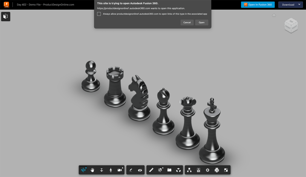
Demo File – Chess Pieces for Tutorial
- Open the Autodesk Fusion shared link: https://a360.co/496kaPN
- Select ‘Open in Fusion 360’ button
- The file will take a few seconds to download. When complete, your browser will prompt you to allow the application to open it. Select ‘Open.’

Mold Release Products and Tips
Creating 3D Printed molds can be a fun and easy way to make duplicates, without having to 3D Print each object!
- In general, use a soft mold material (TPU) when casting a hard material (Resin, Plaster, etc) OR use a hard mold material (PLA Plastic) when casting a softer material (Smooth-On Vytaflex 30).
- I recommend many Smooth-on products which can be found at local distributors around the globe. They do also sell (select) Smooth-on products on Amazon, just be cautious of the prices as they tend to fluctuate more on there (from 3rd party sellers)
- Universal Mold Release is by far my favorite ‘mold release’ product.
- In a pinch, you can try using PAM, Olive Oil, or Vaseline – though results with these vary significantly based on the type of material you cast.
Transcript
Welcome to Day #22 of Learn Fusion 360 in 30 Days. I’m Kevin Kennedy,
and today we’ll discuss the core workflow for creating two-part molds, including registration pins, clearances, and more.
To start, open the demo file which includes these example chess pieces.
Before we create the outer mold box, we’ll want to consider our parting line.
A parting line is the line between the two halves of the mold.
Our X-axis, where the reference line is sketched, can serve as our parting line. With that in mind, we’ll want to ensure our objects are all in their ideal position.
We’ll want symmetrical objects to be placed so their symmetry line matches our parting line, retaining the symmetry.
For non-symmetrical objects, we’ll want to consider if the position will affect the outcome of the mold.
Starting with the King, you’ll see that we’ll be splitting it down the symmetry line, so nothing to change here.
The Queen is also symmetrical in shape. However, these small areas are less than ideal for a parting line, as we want to avoid brittle areas. To solve this, let’s go ahead and rotate the Queen 45 degrees by editing our Joint.
For your convenience, I’ve labeled the Joints in the Browser. We can right-click and edit the Queen Joint. Rotate this 45 degrees. Our parting line will now cut the model where there is additional geometry. Small detailed areas can be problematic when aligned with the parting line.
Our Bishop is symmetrical, but it’s not in the correct position. Let’s edit the Bishop Joint and rotate this 90 degrees. Its symmetry line now matches our parting line.
The Knight looks correct, so we can move on to the Rook.
Currently, the parting line would be close to this Extrusion. However, this one is a bit tricky the way the top extrusions are spaced out. Let’s go ahead and rotate this 10 degrees, allowing our parting line to run down the middle of each stub.
Lastly, the Pawn is ready to go so we can proceed by creating our outer mold box. We’ll then cut away the positive chess shapes and discuss registration pins and clearances.
First, let’s create a new component in the Browser for our “Mold Box.”
We’re going to make a simple box that surrounds all of the chess pieces, so let’s sketch a rectangle on our bottom origin plane. Remember you can quickly activate Rectangle with the keyboard letter “R.”
Before selecting the origin point, let’s switch our rectangle to the “Center Point Rectangle.” This will allow us to define the length and width from the Origin Point, since the chess pieces are centered from the origin.
We’ll make the length 450mm and the width 90 millimeters. In general, these dimensions just need to be larger than your object, accounting for enough material on the outer edge of the mold design.
We’ll then Extrude this beyond the King to a height of 160mm.
We’re now ready to subtract our positive chess shapes from the outer mold box. Similar to our one-part mold on day number 21, we’ll achieve this by using the Combine command.
Once active, select the Mold box as the “Target Body.” The “Tool Bodies” will be each of the six chess pieces. Remember you can select them in the Canvas, which is our model, or we can select them in the Browser.
Double-check that we have all six selected and we’ll change the operation to ‘Cut.’ We’ll also check “Keep Tools.” I always recommend keeping the ‘tools’ in case you need to make design changes later.
With our chess pieces removed from the mold, we’ll now create our parting line.
I set up the demo files from the center of the origin which will allow us to use the origin plane as our cutting plane. However, when designing for mold making, you can also use any of the construction planes to create precisely placed parting lines. This is helpful when you need to create 3-part molds or other mold types that have more than one parting line.
Activate the Split Body command.
Similar to the Combine command, start by selecting the body to Split, which is our mold body. We’ll then choose our XZ origin plane as the “Splitting Tool,” as this origin plane aligns with our parting line. Notice it’s highlighted in Red helping us double-check the splitting direction.
After selecting OK, we’ll have two different 3D bodies in the Browser. Let’s rename these “Left” and “Right” so it’s easier to place our registration marks.
Registration marks, which are sometimes referred to as “Keying,” is the process of adding unique stubs on one half of the mold and corresponding indentations on the other half of the mold. This allows the mold parts to quickly line up with accuracy.
Registration marks are commonly created with half spheres or other common geometric shapes.
I’ll hide the Left body and right-click to create a sketch on the Right body.
I recommend a minimum of 3 registration marks to help align the mold. Large molds may require additional.
Because spheres don’t print as well as other shapes, I also recommend using triangles or polygons for your shapes.
Take a few minutes to add three or four registration marks around the mold. Be sure to keep them approximately 5mm or more away from the edges, or the mold cavities.
You’ll also find it helps to place them randomly, allowing the mold cavities to only work in a single direction. This is particularly helpful when your design is in the middle of the mold.
Optionally, you can use the sketch dimension tool to precisely place the sketches away from the edges. Something like this is where it can be deemed okay to not fully define your sketch, allowing you to click and drag the Stubs around after they’re cut out of the other half of the mold.
Let’s Extrude each sketch profile to a distance of 8mm.
Once our registration marks are sticking out on one side of the mold, we’ll need to cut them out on the opposite side.
We can do this using the Combine command, just as we did with the Chess pieces.
Turn the Left body back on and activate Combine. After selecting the Left half as the Target Body, we can select the Right half as the Tool Body. This is because our stubs joined the existing 3D body. Had we set the Extrude feature to create ‘new bodies,’ we could instead select the stubs individually.
We’ll double-check the Operation is set to Cut and the Keep tools option is checked.
Once complete, let’s hide the Right body and take a look at the results.
All of the registration indentations should now appear. However, we must factor in a small clearance for the 3D printing process.
In our case, we’ll want to add a total of 0.15mm in clearance, which is a good starting point.
We can achieve this clearance with the Offset Face command.
Once active, we can do a window selection over the first registration indentation. This should have a total of seven faces selected. The individual back face and the six side faces.
We can hold down the Shift key and complete window selections over the remaining indentations. Double-check you didn’t select any mold cavity or other faces during this process.
Once everything is selected, we’ll subtract 0.075mm, because the offset is taking place on both sides.
As an optional step, I like to add Chamfers to all the outer edges of the mold box. Take a minute to play around with some different sizes. These Chamfers can help reduce some of the material and get rid of the sharp corner edges that are prone to warping.
Last but not least, we need to consider whether the mold needs a cavity for pouring the material.
When the design has a flat bottom, such as our chess pieces, you’ll find it easiest to use the flat portion as the pour cavity. This is why we created our mold box from the bottom instead of encasing the entire object.
When the object does not have a flat portion, I recommend using the Hole command to create a pour cavity with a chamfered edge.
In addition to the pouring cavity, multi-part molds work best when they have a vent hole. This allows air to escape as the material flows into the void.
This will reduce the potential of air bubbles getting trapped, as well as help smaller details come out well.
Vent holes can be done with a simple Extruded circle, or you can make them by sweeping a circle into the cavity.
You’ll also want to consider any objects that may be too small for the mold.
The tops of our Queen and some other pieces may not come out well depending on the materials used. Consider removing them, as well as filling in any voids that may be too small.
Don’t forget certain designs and materials may require a 2 to 5-degree draft angle, similar to the one-part mold in the previous lesson.
[Upbeat Music]
I’ll see you on Day #23 where we’ll discuss assemblies and Joints in Fusion 360.
[Upbeat Music]