Making CAD education accessible to anyone, anywhere.
We hope you’ve been enjoying the wealth of free Fusion training provided by Product Design Online. Our commitment to empowering individuals like you with valuable skills is at the core of what we do.
If you’ve found our free content beneficial in your learning journey, we kindly ask for your support through a donation. Your contribution will not only help sustain the availability of free materials but also enable us to expand our offerings and reach even more learners globally.
Please select a donation method
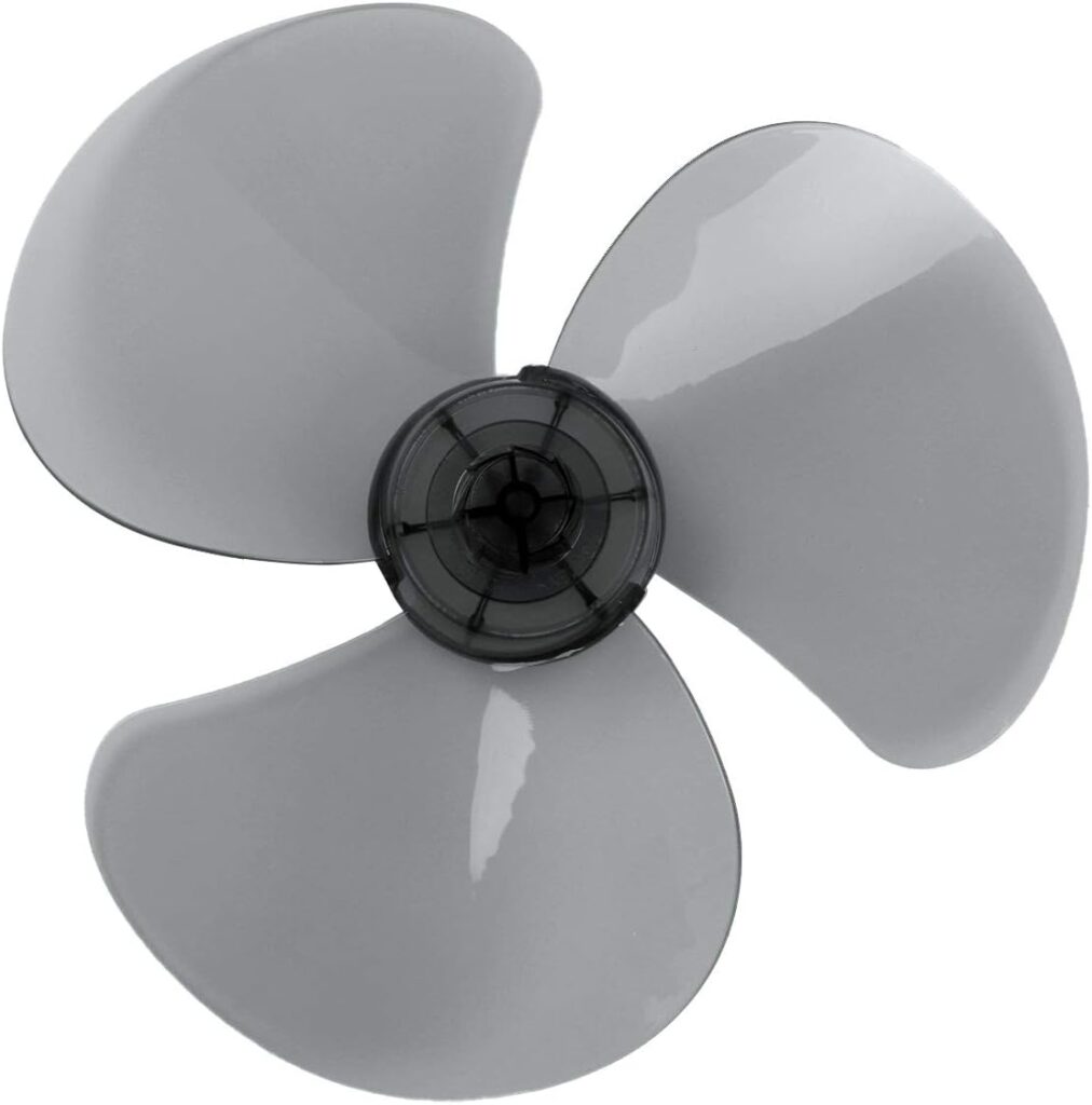
Propeller Reference Image

Key Terminology for Surface Modeling in Autodesk Fusion
- Surface: In Fusion, a surface is an outer skin that represents the shape of a model. Unlike solid bodies, which are closed volumes, surfaces are open and do not enclose a volume. Surfaces represent the exterior of a shape without defining its interior. As we’ll see later in this lesson, surfaces do not represent real 3-dimensional volumes until we convert them to solid bodies.
- Patch: A Patch represents a single surface. The Patch tool is designed to generate surfaces by filling in gaps or connecting edges and curves. It is commonly used where you need a continuous surface between edges.
- Edge: An edge is a line segment that defines the boundary of a surface or face in a 3-dimensional model. It is where two faces or surfaces meet. An edge can be straight or curved.
- Boundary: A boundary is the outer perimeter or contour of a surface. Boundaries define the limits of a surface and are composed of one or more edges. In surface modeling, edges and boundaries are essential for defining the shape and extent of surfaces. These terms are within many surface tools, including the Patch and Loft tools.
Transcript
Welcome to Day #25 of Learn Fusion 360 in 30 Days. I’m Kevin Kennedy, and today we’ll look at the fascinating world of surface modeling while creating a propeller. Pay close attention, as these beginner surface modeling tips will transform how you design in Fusion.
To get started you’ll need to know some basic terminology. The first term is surface.
In Fusion, a surface is an outer skin that represents the shape of a model. Unlike solid bodies, which are closed volumes, surfaces are open and do not enclose a volume. Surfaces represent the exterior of a shape without defining its interior. As we’ll see later in this lesson, surfaces do not represent real 3-dimensional volumes until we convert them to solid bodies.
The next term is Patch. A Patch represents a single surface.
The Patch tool is designed to generate surfaces by filling in gaps or connecting edges and curves. It is commonly used in scenarios where you need a continuous surface between edges.
The third term is an Edge. An edge is a line segment that defines the boundary of a surface or face in a 3-dimensional model. It is where two faces or surfaces meet. An edge can be straight or curved.
The last term is Boundary. A boundary is the outer perimeter or contour of a surface. It defines the limits of a surface and is composed of one or more edges.
In surface modeling, edges and boundaries are essential for defining the shape and extent of surfaces. You’ll see these terms within many surface tools, including the Patch and Loft tools.
Start by creating a new component and make sure it’s active.
Within our component, we’ll insert the propellor reference image. This is not required but will help us sketch the shape of the blade.
Use the Canvas feature to insert the provided image on the XY origin plane.
Remember to select the origin plane tied to the component, not the assembly.
Once inserted, we’ll calibrate the reference image from the Browser. Selecting two points will allow us to define the approximate 40mm diameter of the hub.
We’ll also edit the canvas to adjust the position of the image, making the center roughly lined up with the center origin point.
Once complete, we can start sketching our hub with a center circle on the bottom origin plane. We’ll define the diameter as a matching 40mm.
Remember our reference image is to serve as a guide. It doesn’t have to be perfectly aligned.
We’ll do a solid Extrude, adding 30mm of thickness to the center hub.
We have the foundation complete and we’re ready to start surface modeling a blade. We can simplify the surface modeling by focusing on a single blade because our propeller includes three of the same blades.
Surface modeling is often easier by breaking down designs into smaller views or sections. Rarely should you be completing everything in one modeling feature.
Similar to solid modeling, many surface modeling workflows require us to start with 2-dimensional sketches. You’ll also find the Surface tools include familiar commands such as Extrude, Loft, Sweep, and Revolve.
A basic propeller blade is curved along the root, where the blade meets the hub. We’ll sketch a simple arc inside our hub body.
To sketch in the desired area, we’re going to make an offset plane that is 12mm away from the center. This distance puts the plane in the approximate area where the blade edges come together.
Sketch out a 3-point arc. For this lesson, we won’t fully define our sketches. This will allow us to make some adjustments on the fly once we have completed our surfaces.
We’re going to create our first surface with the Surface Loft command. This means we need a second line to loft to, which is the outer edge of our blade.
We’ll Create a second offset plane that is 100mm away from the center.
When surface modeling, it’s better to extend surfaces past the desired shape, as a common workflow is to trim away the excess surfaces.
We’ll sketch a straight line on this offset plane.
Looking at the sketch from a top view, we need to imagine that the endpoints of our lines connect to the endpoints of our arc. This line must be large enough that our final lofted surface encompasses the full width of the blade.
Take a first pass at this, knowing you can always extend the lines later.
With our two sketches complete, we can head to Fusion’s Surface tab. The Surface tab organizes all of Fusion’s surface modeling features. Notice they are distinguished by their orange color, while solid modeling tools are blue.
Let’s activate the orange surface Loft tool.
On Day 4 we lofted the complex bottle shape using four closed sketch profiles.
One key difference between surface modeling and solid modeling is that our surface Loft tool does not require closed sketch profiles.
We can simply select our Arc, followed by the second line.
Two edges or profiles are the bare minimum for our surface Loft.
We now have our first surface body in the Browser. Notice this has a matching orange icon indicating it’s a surface and not a solid.
Let’s turn off the visibility of this surface, allowing us to focus on sketching the edge of our blade.
Start a new sketch on the XY origin plane.
Use the Fit Point Spline tool to sketch the rough shape of the blade. Using the fewest amount of spline points will help us create smoother curvature.
We’ll also want to ensure we start and end within our hub.
Because we’re creating a surface, we do not need to make this a fully closed sketch profile.
With the Surface Extrude command, we’ll select our spline and Extrude it at least 30mm. This distance does not matter as long as it’s past the top end point of our arc. I’m choosing 30mm knowing it’s the top of the hub.
Notice we did not need a closed sketch profile with our Surface Extrude. You’ll find that surface modeling often requires less detailed sketches when compared to solid modeling.
In the Browser, let’s turn on the original surface body. Notice we’re getting closer to our desired shape of the blade!
We’ll need to trim away the excess of the blade to achieve the final shape.
We can quickly remove unwanted surface areas with the Surface Trim tool. Note that surface Trim is different from the sketch trim tool.
Start by selecting a trimming tool.
Our second surface body should be the trimming tool because it represents the outer contour.
We’re then prompted to select ‘surfaces to remove’. We can select any part of the surface that is outside our desired blade shape.
After selecting OK, we can hide the second surface body, leaving us with our desired blade shape.
Because we didn’t fully define our sketches, we can now turn those back on and adjust the endpoints of the arc or our straight line. This will allow us to change the cupping of the blade in real-time.
Don’t forget that our line must extend past the width of our blade or the surface won’t be large enough to cut out the entire contour! You’ll find it leaves us with an unwanted straight edge.
We may also want to make the long straight line at an angle, further adjusting the design of the blade. This may require you to delete a horizontal constraint.
Currently, our blade is still a surface body. Remember that our surface body does not represent real volume until we convert it to a solid body. You can test this by exporting your model as an STL file.
As a result, only the hub body will have real volume.
We’ll need to use the Thicken command to convert our surface body to a closed volume, otherwise known as a solid body.
However, we also want three blades. We can use the Circular Pattern command to create the remaining blades.
You’ll find the Faces option within our modeling pattern features. This allows us to select faces or surface bodies. You’ll find this takes less computing power than patterning solid bodies or individual features.
Once selected, define our center axis and change the quantity to three.
We can finish the model by converting our three surfaces into solid bodies.
With the Thicken command, select the desired surfaces and define the desired blade thickness.
This results in a single solid body for each blade, resulting in four solid bodies in our Browser.
If you export the component again, you’ll find the blades are included as they are solid bodies representing real volume.
If desired, we can use the Combine tool to join these four solid bodies together, resulting in a single solid body.
You’ve successfully completed a propeller with Fusion’s surface tools!
[Upbeat Music]
I’ll see you on Day #26 where we’ll take an introductory look at Autodesk Fusion’s Mesh tools.
[End Upbeat Music]