Learn Autodesk Fusion in 30 Days (formerly called ‘Fusion 360’) is the most popular Fusion course online and was first launched in 2019. Since then, we have launched a revised 2023-24 version, and we are now releasing a fully updated and improved 2026 version.
This is Day #2 of the 2026 Revised version of the course.
Full Course on YouTube
Watch the full course in this official PDO YouTube playlist.
Get the 15-day Bundle of Companion Guide (Step-by-step PDFs)

Grab the official, step-by-step PDF guides and build your CAD mastery on a rock-solid foundation of practice projects and challenges. Serves as a standalone guide or the perfect companion to the video lessons.
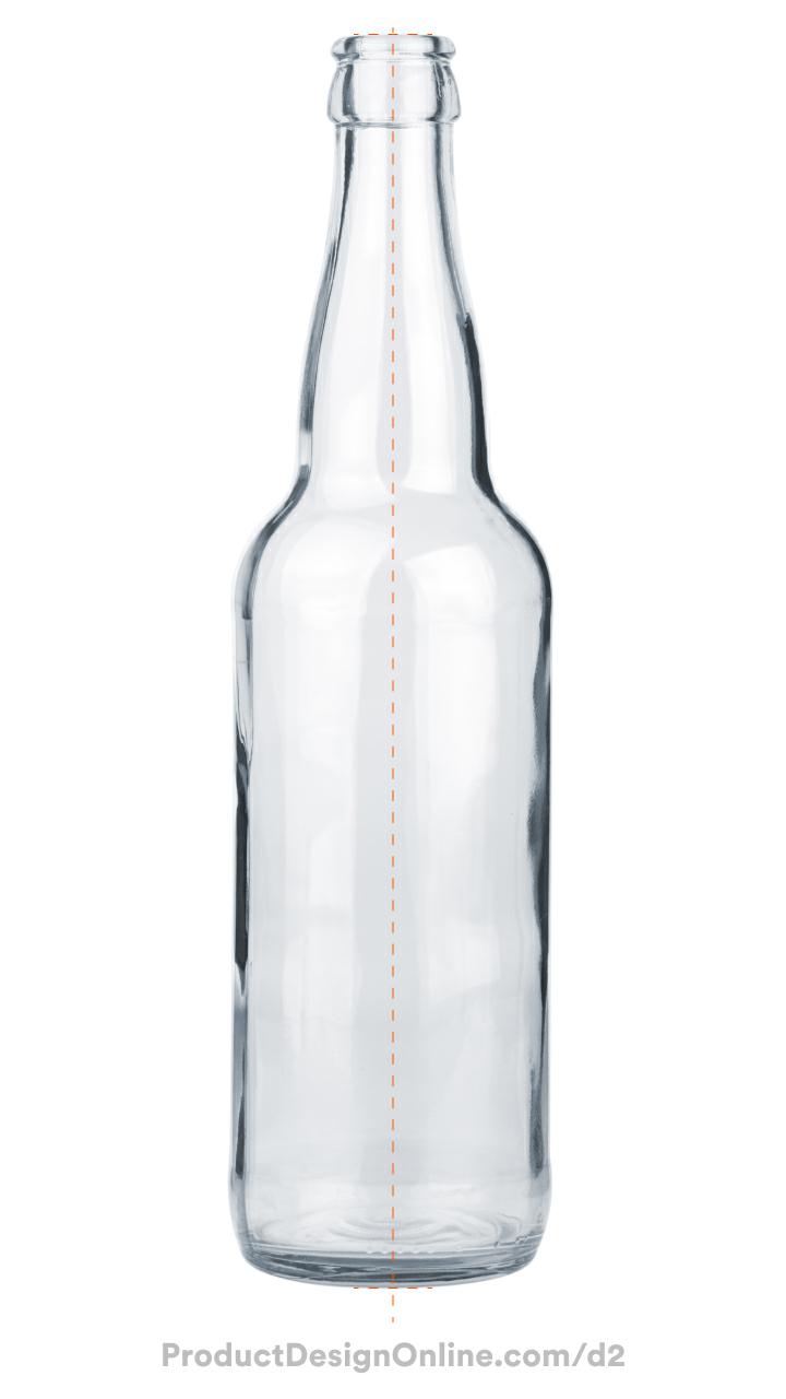
Reference Image
Click the Download button to download the free reference image to use with Day 2.
Making CAD education accessible to anyone, anywhere.
We hope you’ve been enjoying the wealth of free Fusion training provided by Product Design Online. Our commitment to empowering individuals like you with valuable skills is at the core of what we do.
If you’ve found our free content beneficial in your learning journey, we kindly ask for your support through a donation. Your contribution will not only help sustain the availability of free materials but also enable us to expand our offerings and reach even more learners globally.
Please select a donation method
Transcript
Your second challenge in Fusion starts right now: modeling this glass bottle. I’m Kevin Kennedy, and this is Day 2 of Learn Fusion in 30 Days. Today, we’re reinforcing concepts from Day 1, while you learn to use reference images, revolve sketches, and add real appearances. Let’s get started!
[transition]
Start a new design file using the Part Design option, since this bottle represents a single manufacturable object.
Click Save in the applications bar and name the file “Day 2 Glass Soda Bottle.
Select the Project and folder you created on Day 1. Double-click the folder to set the correct save location.
Starting your file with a reference image can be a great way to reverse-engineer designs instead of guessing shapes.
Download the reference image via the link in the video description.
In Autodesk Fusion, the Canvas tool allows you to insert reference images. Activate Canvas from the Solid toolbar or the Insert menu.
Once active, choose an existing reference image from a Project or Folder, or click “Insert from my computer” to locate the file on your hard drive.
Select the Day 2 reference image from your downloads folder and click Open.
Pick the front origin plane when Fusion prompts you to select a planar face or sketch plane. This ensures you sketch the bottle from the front view, which matches the view of our reference image.
The Canvas dialog offers several options to modify your image, including changing opacity, scale, and orientation.
Notice the text is flipped. Select the Horizontal Flip button to correct the flipped text.
Manipulators on the Canvas allow you to scale the image. Avoid the horizontal and vertical controls, as those will distort the proportions. Click and drag the corner manipulator to scale the image.
We’ll calibrate the exact size in a minute. For now, practice scaling the image.
Click OK in the Canvas dialog.
A Canvases folder now appears in the Browser. Right-click the Canvas name to find the Calibrate tool.
Calibrate allows you to select two points on the image and then define the distance between them.
Remember, you can use the scroll wheel on your mouse to zoom in and out. Pan by holding the scroll wheel and moving your mouse.
Zoom into the orange reference lines at the bottom of the image and click once to place the first point of the calibration.
If you misclick, press Escape and reactivate the Calibrate tool.
Use your mouse or the Pan tool from the Navigation Bar to move to the top of the reference image. Press Escape to exit the Pan tool if you selected it from the navigation bar.
Set the second calibration point by clicking on the orange reference line at the top.
Notice a dimension appears. Define the distance as 240mm.
Watch what happens as I press the Enter key.
The reference image now scales to the 240mm length . Tracing this image ensures you create the model at a 1:1 scale, which is critical for 3D printing or manufacturing.
Before we sketch, the bottom of the bottle must be aligned with the origin. This ensures the origin is positioned at the very base of the bottle, effectively placing it on our bottom origin plane and allowing us to start our sketch from the origin.
Edit the Canvas feature. Double-click it in the parametric timeline.
Drag the vertical directional arrow to move the image upward until the bottom of the bottle meets the origin point.
You may need to zoom in or out, because the arrow snaps every 10mm. To be more precise, enter a value like 112.70mm in the Y distance field. I got this number through trial and error.
Click OK in the dialog.
Our reference image is all set. We can now sketch the outline, which we’ll soon turn into a 3D body using the Revolve tool. Stick around for the Shell command, as today I’ll show you a timeline trick that fixes a mistake most beginners make.
When you insert a Canvas, Fusion will automatically hide the origin folder.
Let’s turn it back on in the Browser.
You can then right-click on the front Origin plane to select Create Sketch from the Marking Menu.
Turn off the Origin folder so it doesn’t block the sketch.
To create symmetrical objects, you only need to draw half of the profile. The Revolve command spins the sketch profile 360 degrees to generate the 3D bottle.
Activate the Line tool.
Click the origin point to start the first line. This line will run straight up the bottle with a length of 240mm.
Locate the Vertical Sketch Constraint icon before clicking to place the line. This constraint snaps the line into a vertical position and locks it there.
Sketch constraints are a best practice that helps you drive parametric designs; we will cover them extensively throughout this course.
Press the Escape key to clear the Line command.
Here’s a pro tip. Press Spacebar to repeat the last used command. This reactivates Line, allowing us to start a new line.
Start at the origin again and draw a line 30mm long. Click to place the line, when the line is horizontal. Notice that the software automatically adds a perpendicular constraint, maintaining a perfect 90-degree angle from your first line.
This maintains a flat bottom for the sketch. Keep in mind that the bottle in our reference image is not a perfect straight-on view. At the end, we’ll also round the edges with a fillet.
Notice the Line command remains active. Continue by sketching a vertical line 130mm long. Click again to place the endpoint.
Press Escape to clear the command. Don’t worry if you mess up a sketch; simply select the object and press Delete on your keyboard. Then, re-sketch the line as needed.
You will also find that you often need to click and drag dimension values out of the way so they don’t block the sketch.
The “Fit Point Spline” tool creates curved sketches, making it easier to trace the bottle’s stem.
Activate Fit Point Spline from the Toolbar.
Start by clicking the endpoint of the vertical line. When sketching with splines, use the fewest number of points possible to simplify the curvature and create smooth, realistic transitions.
Take your time to zoom in and click to place each point where the curvature changes. There should be approximately 10 different spline points. These do not have to be perfect, as you can adjust them later.
Once you finish placing points, press the Enter key or select the green checkmark icon. This step is important: pressing Escape before you “end” the tool with the checkmark or Enter key will delete your spline geometry.
Now, take a minute to clean up the spline. Each spline point provides a handle to adjust the curvature.
Press Escape to clear the command.
Click in space to deselect the spline, which hides the handles.
Before you move those handles, click and drag the points themselves to reposition them. This step alone can improve the curvature.
Next, you will want to select individual spline points… then, click and drag the spline handles to match the curvature of the reference image.
Keep in mind that the length of the spline handle controls the “weight” of the curve, while the angle controls the direction.
Very important: avoid pulling the handles too far in either direction, as it creates “kinks” or “self-intersecting geometry” that will break the Shell tool later.
Expect some trial and error as you move between repositioning points and adjusting their handles. Use the Undo button in the application bar to revert any unwanted changes.
Here’s a pro tip: When working with sketch curvature, always consider how it transitions into straight lines. Select the bottom spline point and check if the handle sits perfectly parallel with the vertical line. If it doesn’t, the transition from the spline to the straight line won’t be smooth.
In Fusion, you can force spline handles to snap to specific directions using constraints. Select the spline handle, then select the Vertical sketch constraint.
Press Escape to clear the constraint command.
Next, Zoom in on the top section, where we’ll finish off the bottle sketch.
Activate the Line tool and start a new line from the endpoint of the vertical line, sketching to the right. Click to place the line without applying a dimension yet. Ensure the software automatically applies either a perpendicular constraint in the corner or a horizontal constraint to keep the line horizontal. This is because we need a flat planar surface for the Shell command to work later.
Let’s connect the endpoint of the fit point spline.
Select the Coincident constraint in the toolbar. This forces two sketch objects to lock together.
Select the endpoint of the horizontal line and then the endpoint of your fit point spline.
This results in a fully closed sketch profile. Fusion represents a closed profile with light blue shading. If I clear the active command, notice I can now select the profile.
If your sketch isn’t shaded blue, your lines aren’t connected. Zoom in on the corners. Usually, a line sits just a hair’s width away from the other. Click and drag the end to snap to the adjacent line, or delete the lines and sketch again.
Before we revolve, we’ll want to do one last very important step.
Use the Sketch Dimension tool to apply an 11mm dimension to the top horizontal line. This ensures the bottle width remains large enough.
Activate Sketch Dimension and select the line. Set the dimension above the line, define the value as 11mm, and press Enter.
Press Escape to clear the command.
Ensure the top spline point does not create a rounded edge, as you will fillet the upper edge of the bottle later. This step is critical, as many users encountered issues here in the previous lesson.
Select the top spline point and verify the handle sits at an angle to this line. It should not be horizontal or create a small, rounded edge.
In a minute, I will also discuss other common issues to watch for when we Shell the 3D body.
Activate Revolve from the Solid toolbar. Ensure you select the blue Revolve icon for solid tools rather than the orange icon for surface tools. We’ll discuss surface modeling later in this course.
The Revolve tool takes your selected profile and rotates it around the defined axis. The tool usually selects the sketch profile automatically since only one profile exists. If not, you can always select it manually.
The Revolve tool then requires an axis to revolve around, such as your center line. However, instead of manually selecting the axis, I want to show a newer Fusion feature that helps when you work on symmetrical parts.
Cancel the Revolve tool and return to the sketch. Remember, you can always double-click the sketch in the parametric timeline.
On Day 1, we used a construction line to find the midpoint. Select the center vertical line and turn it into a construction line.
If you recall, construction lines are not referenced by sketch profiles. Notice how the profile is no longer fully closed or selectable. This is where Fusion’s centerline feature comes into play.
Select the line again and select Centerline in the Sketch Palette. Visually, centerlines use a distinct dash-dot pattern to differentiate them from the standard dashed construction line. A centerline still provides a fully closed sketch profile… and watch what happens when I reactivate the Solid Revolve tool.
The Revolve tool automatically uses the centerline as the axis to revolve around. This is a new best practice for setting up your sketches. Let me know in the comments if you already knew about the centerline option.
Keep in mind that you can clear the axis if you ever need to select a different one.
Generally, Revolves use 360 degrees to complete the object. However, in some scenarios, you may need to alter the degrees. Do this with the rotation slider or in the dialog box.
Click OK to save the Revolve.
We no longer need the reference image. Hide the reference image by selecting the eyeball icon for the image or the Canvases folder in the Browser.
If you’re brand new to 3D modeling, you may notice a line down the side of the model. Most software programs include this to help you better understand the 3D shape.
Go to Display Settings > Visual Style > and select the Shaded option. Notice the edge line disappears. This Shaded style helps you inspect the curvature of your designs.
I’ll change this back to the default: Shaded with Visible Edges Only.
We’ll now hollow out the bottle using the Shell command, similar to the toy block from Day 1.
Activate Shell. Select the top face of the bottle. Define the shell thickness as 2.5mm.
If you receive an error message, let me know what it says.
If Shell allows you to select the top face but throws an error as you define the thickness, your spline geometry likely has an issue. Remember, the shell traces the entire outer contour. If the contour contains a curve too sharp for the defined thickness, the Shell will fail. You will need to adjust your spline handles. It will more than likely be the one in this top area.
Let’s finish the bottle with fillets and a realistic glass appearance.
As you design in Fusion, you will often need to apply a feature before the Shell command so it accounts for the geometry as it traces the contour. In this case, we want to fillet the bottom edge of the bottle with a 5mm radius to create a soft, rounded edge.
However, applying it now is not ideal because we only have a 2.5mm wall thickness, which creates a thin spot in the corners. Instead, we need to apply this fillet before the Shell command so the shell follows the curve as it calculates the thickness.
This is one of the great benefits of using a parametric modeling program. In Fusion, you can either roll back the timeline to before the Shell and apply the desired Fillet… or, if you already created the Fillet, you can click and drag the feature. I’ll release it just before the Shell. This tells Fusion to process the 5mm Fillet first, then the Shell.
Notice this fixes the geometry, as the Shell command now accounts for the 5mm radius.
For the top lip of the bottle, add 1mm fillets after the Shell.
Activate Fillet and select the top two edges. Define a fillet radius of 1mm to ensure the edges are not sharp.
Appearances are visual representations of materials that help you better visualize your designs.
Activate Appearances from the Modify menu or with the shortcut A for ‘Appearance.’
Once active, search through the available materials. Find the Glass folder and the Smooth folder within it. You must download each appearance the first time you use it.
Click and drag, and release the material over the model.
The glass appearance helps you see the thickness created by the Shell command.
Experiment with some different appearances. Drag and drop a new appearance to override the previous.
Great job completing the glass soda bottle! Don’t forget to save your design and click here for Day 3, where you’ll learn the magical Sweep command to create a paperclip!