Learn Autodesk Fusion in 30 Days (formerly called ‘Fusion 360’) is the most popular Fusion course online and was first launched in 2019. Since then, we have launched a revised 2023-24 version, and we are now releasing a fully updated and improved 2026 version.
This is Day #3 of the 2026 Revised version of the course.
Full Course on YouTube
Watch the full course in this official PDO YouTube playlist.
Get the 15-day Bundle of Companion Guide (Step-by-step PDFs)

Grab the official, step-by-step PDF guides and build your CAD mastery on a rock-solid foundation of practice projects and challenges. Serves as a standalone guide or the perfect companion to the video lessons.
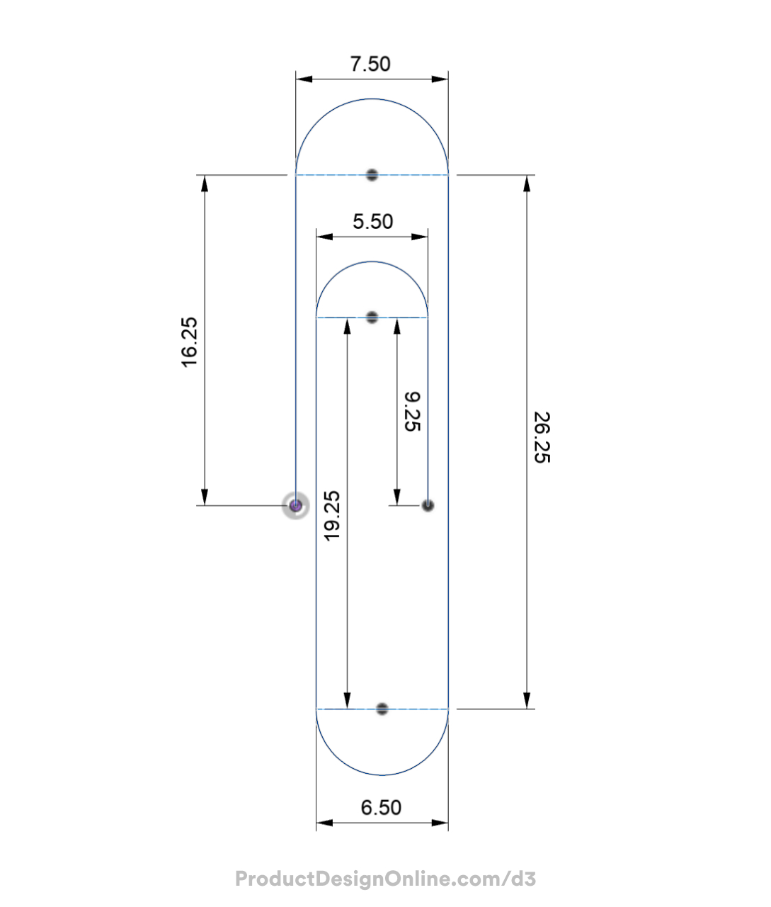
Paperclip Dimensions
Click the Download button to download the free image to reference the Day 3 dimensions.
Making CAD education accessible to anyone, anywhere.
We hope you’ve been enjoying the wealth of free Fusion training provided by Product Design Online. Our commitment to empowering individuals like you with valuable skills is at the core of what we do.
If you’ve found our free content beneficial in your learning journey, we kindly ask for your support through a donation. Your contribution will not only help sustain the availability of free materials but also enable us to expand our offerings and reach even more learners globally.
Please select a donation method
Transcript
Your third challenge in Fusion starts right now: modeling a paperclip. I’m Kevin Kennedy, and this is Day 3 of Learn Fusion in 30 Days. Today, we’re using this everyday object to master the Sweep tool and professional sketching habits. Let’s get started!
Start with a new Part Design file and save your design.
The Sweep tool creates a 3D shape by moving a 2D profile along an open or closed sketch path.
We’ll first sketch the path of the paperclip, followed by the circular profile.
Similar to the toy block on Day 1, imagine the paperclip lying flat on a table. We’ll sketch from the top view.
Activate Create Sketch and select the bottom XY origin plane. Fusion automatically reorients the view to look directly at the sketch plane.
Activate the Line tool with the keyboard shortcut L for line.
Follow the best practice of starting at the origin point.
For your convenience, I’ve linked to a reference image below to help you follow along with all the dimensions.
Sketch the first line vertically at a distance of 16.25mm. To “fully define” this sketch, we’ll use sketch dimensions and constraints to lock each line in place.
Click to place the line where it snaps vertically. A vertical glyph will appear to represent the vertical sketch constraint.
Remember, the line command remains active, allowing you to continue creating lines until you press the Escape key to exit.
Create a line running to the right at a distance of 7.5mm. This line serves as the overall width, excluding the final profile thickness.
Note the perpendicular constraint that Fusion automatically applies at the corner.
Sketch the next line down 26.25mm. Again, click to place the line where it snaps perpendicular to the previous line. As you sketch, keep an eye on the automatic sketch constraints; you can always select and delete them if needed.
You can also undo and reactivate the Line command if you accidentally snap to the wrong point.
Create a line running to the left 6.5mm as the paperclip gets smaller in size.
Then, draw a vertical line 19.25mm long.
Next, move back to the right 5.5mm.
Lastly, draw back down 9.25mm.
Once you finish sketching, press Escape to clear the Line command.
Notice that all of your sketch lines appear black. These black lines indicate that the sketch is fully defined with constraints and dimensions.
Fully defined lines will not move or update unless you manually change those constraints or dimensions.
In Fusion, the other way to know a sketch is fully defined is to toggle open the Sketches folder in the Browser. A red lock icon appears when the sketch is fully defined. We’ll continue to discuss constraints and this concept in a dedicated lesson later in this course.
Remember from Day 2, you can click and drag dimensions to move them out of the way. It’s always a good idea to move them so they don’t overlap sketch objects.
The Sketch Palette allows you to hide dimensions, constraints, and other geometry. This can be helpful when you need to focus on a certain aspect of a sketch.
To finish the sketch, we need to add the rounded ends.
The three lines that run horizontally are not necessary for our sweep path. These allowed us to keep sketching without reactivating the Line command each time and also helped us define the width of the paperclip.
We do not want them to interfere with the sweep path, so we’ll turn them into construction lines.
Hold down the Shift key and select the three horizontal lines. Right-click and select the Construction option from the Marking Menu.
Remember, construction lines are dashed lines and will not affect the sketch profile.
We’ll use the Tangent Arc tool to sketch the rounded ends of the paperclip shape.
You’ll be activating tools frequently in Fusion. One tip is to press the keyboard shortcut letter ‘S’. This opens the Shortcuts box, where you can type out the desired feature.
Type out tangent. Notice we have a few options. Select the Tangent Arc to activate it.
Once active, click the two endpoints where our construction lines run. Make sure to click where it snaps to the endpoints.
Notice the Tangent Arc tool automatically applies a tangent constraint to the curve and the adjacent line. This tangent constraint ensures smooth geometry throughout the transition, which is ideal in preparation for the Sweep command.
Repeat this process for the remaining two ends. Double-check that you see the Tangent icon for each one. If not, delete the arc and sketch it again.
Our path is now complete.
A best practice in Fusion is to rename your objects in the Browser. This includes sketches, bodies, and so on.
Press Escape to clear any commands and click the name once to select it and a second time to edit it. Name this ‘Sweep Path.’ Naming your sketches makes parametric modeling easier, especially when you work on larger projects.
Select “Finish Sketch” and view the model from the Home position.
To create a Sweep that follows this paperclip shape, you need a Sketch Profile. In this case, we’ll use a standard circle, as a paperclip is a round piece of steel bent into a looped shape.
Since you followed the best practice of starting at the origin point, you can sketch on the front XZ plane to create the profile.
Toggle open the Origin folder in the Browser. Select the XZ origin plane to see a preview and verify it is the correct plane.
From here, right-click the XZ plane in the Browser and select Create Sketch.
This offers yet another way to create a new sketch in Fusion. As you learn Autodesk Fusion, you’ll find many different ways to activate features.
Activate the Center Diameter Circle with the keyboard shortcut C for Circle.
Select the origin point for the center of the circle.
This represents the paperclip’s thickness, which generally ranges from 0.5 to 1mm. I’ll define mine as 0.75mm, but you can choose your desired thickness. Remember to click to place the circle.
Looking at the model from the Home position, you now have everything necessary to complete a Sweep: a path and a sketch profile to sweep along it.
Activate Sweep from the Create menu of the Solid tab.
Note that Autodesk Fusion also includes the Sweep command in the Surface and T-spline modeling environments. Ensure you activate the blue Solid modeling Sweep.
You will notice that Fusion supports other types of Sweeps. Use the default “Single Path” option since we have only one path. For future reference, keep in mind that sweeps can become more complex by using additional guide rails.
Similar to the Extrude and Revolve commands, start by defining the sketch profile.
Select the profile circle by clicking inside it.
Choose the Path selector in the Sweep dialog to select the sketch path. Before you click, notice the Chain Selection option is checked by default. Chain Selection automatically selects all sketch objects that touch or “chain” together.
In this case, it allows you to select the entire path with a single click.
If I clear the selector in the dialog and uncheck “Chain Selection,” you can select individual sketch entities. Neither method is right or wrong; your choice often depends on the specific project and your desired outcome.
Lastly, you can change the distance the Sweep follows. Either drag the directional arrow on the model or define a distance value in the dialog box.
This distance often confuses beginners because it does not use units of measure.
Instead, Fusion uses values between 0 and 1, where 1 represents 100% of the path. For example, type 0.5 to sweep across half, or 50%, of the path.
As you can see, the Sweep tool allows you to quickly create various shapes. Spend some time practicing sketching other basic paths and try sweeping different profile shapes.
Great job completing your paperclip! Don’t forget to save, and I’ll see you on Day 4, where we’ll dive into one of the more error-prone but rewarding tools in Fusion, as you create a complex glass bottle.