Learn Autodesk Fusion in 30 Days (formerly called ‘Fusion 360’) is the most popular Fusion course online and was first launched in 2019. Since then, we have launched a revised 2023-24 version, and we are now releasing a fully updated and improved 2026 version.
This is Day #11 of the 2026 Revised version of the course.
Full Course on YouTube
Watch the full course in this official PDO YouTube playlist.
Get the 15-day Bundle of Companion Guide (Step-by-step PDFs)

Grab the official, step-by-step PDF guides and build your CAD mastery on a rock-solid foundation of practice projects and challenges. Serves as a standalone guide or the perfect companion to the video lessons.
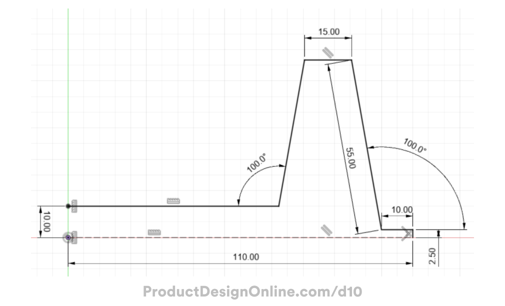
Sketch Dimensions
Use the following sketch dimensions to create the sketch profile for the dog bowl. This image does not need to be inserted into Autodesk Fusion and is provided for you to reference while you sketch.
Making CAD education accessible to anyone, anywhere.
We hope you’ve been enjoying the wealth of free Fusion training provided by Product Design Online. Our commitment to empowering individuals like you with valuable skills is at the core of what we do.
If you’ve found our free content beneficial in your learning journey, we kindly ask for your support through a donation. Your contribution will not only help sustain the availability of free materials but also enable us to expand our offerings and reach even more learners globally.
Please select a donation method
Transcript
Welcome to Day 11 of Learn Fusion in 30 Days. Today, you’ll create a dog bowl while looking at some beginner surface modeling concepts, including offsetting and thickening surfaces. Let’s get started!
Start a new design file by choosing the Hybrid Design intent or changing the intent in the Browser. Then, be sure to save your design.
We will use Hybrid because our dog bowl contains one part for the metal bowl and a second part for the rubber grip.
When working in Hybrid designs, it’s a best practice to create a new component for each part. Activate New Component from the toolbar.
Set the type to Part, as this will represent a single manufacturable object. Although our dog bowl consists of metal, we will stick with a standard component as we won’t utilize the Sheet Metal tools.
Make sure you uncheck External. This creates an ‘internal’ component that lives only inside this Hybrid design file. If you check External, Fusion will create the part as a separate design file.
Most importantly, name this component. Type Metal Bowl and click OK to save the Component.
Notice the component in the Browser. This component serves as a container for everything related to this part, including sketches, surface bodies, 3D bodies, and more.
Get into the habit of creating the components up front once you know how many parts your file requires. Press the Spacebar to repeat the New Component command or activate it from the toolbar.
Set this component to a Part Type as well. Name it Rubber Grip.
Clear out the parent selector. Select the top-level or ‘root’ component to ensure both components live on the same level of hierarchy in the Browser.
Click OK to save it.
Very important: Always keep a close eye on which component you have ‘active’ in the Browser. The dot icon next to the component name indicates the active one.
We will start with the Metal Bowl, so hover over the component and click the icon to activate it. This ensures the component associates with all the features you use. We will later activate the rubber grip component.
Start by sketching half the dog bowl shape, allowing you to revolve the sketch.
Activate Line and select the front XZ origin plane to sketch a side profile.
Click to start the first line at the origin point. Sketch this line to the right 110mm. Click to place the line where it snaps horizontally.
Sketch the next line straight up 2.5mm to represent the thickness of the flange.
The flange will stick out 10mm. Sketch back to the left 10mm and click where the line snaps perpendicular to the previous one.
The next line represents the angled outer wall. Press the Tab key at any time to switch between inputs. Define the angle input as 100 degrees. Press tab to switch to the length and type 55mm for the length. Click to place the line where it heads toward the left.
Head to the left 15mm and click to snap the line horizontally. Notice this adds a parallel constraint, keeping the line parallel to the bottom horizontal line.
We don’t know the length of the last two lines, so click past the desired length on purpose; we will trim away the excess later.
Clear Line with Escape, then press the Spacebar to reactivate it.
Start this line on the left, looking for the dashed reference line as you hover near the origin point.
Click to place this line where it runs past the previous line.
Let’s add a dimension between the two horizontal lines. Activate Sketch Dimension. Select the two horizontal lines and click to place the dimension on the left. Define this as 10mm before pressing Enter.
To clean up sketch segments, use the Trim tool. Activate Trim from the Modify Sketch menu. With trim active, hover over sketch objects. Notice the red preview indicating what will trim away. Click both segments to remove them.
Very important: Use trim with caution. It cleans up sketches effectively, but it may affect sketch constraints, so watch for any removed constraints.
In our case, if you clear the Trim tool with ESC, you will notice that trimming these line segments automatically added a coincident constraint between the two endpoints. This keeps the two lines together; however, notice the sketch is not yet fully defined. This endpoint can still move freely.
Click to clear any active selections and activate Sketch Dimension. Select our angled line and the horizontal line. Selecting two lines allows you to define the angle between them instead of a distance. Click to place the dimension and define the angle as 100 degrees.
If you toggle open the Sketches folder within your Metal Bowl component, you will see that the red lock icon is missing, indicating that the sketch is not yet fully defined.
Notice our sketch point on the left line remains underdefined, appearing white instead of black. Activate the vertical constraint in the toolbar. Select the point and then the origin point. This forces it to stay in place, vertical from the origin, which will never move.
This should fully define your sketch. If you still don’t have the red lock icon, check the 100-degree angle on the right. At times, based on your selection, the angle dimension may automatically generate a construction line. When Fusion does this, the lines often extend freely until you define them.
Activate the coincident constraint and select the endpoint of the dashed reference line and the corner edge. This forces the length of the reference line to stay put, fully defining your sketch.
Surface modeling does not require a fully closed sketch profile like Solid modeling. You do not need to close off the left opening. This concept distinguishes surface modeling from solid modeling. Generally, you can use less sketch geometry to accomplish similar results.
Let’s turn the bottom line into a construction line, as we will not need it in our surface body. Press ESC to clear the active command, select the bottom line, and click the Construction option in the Sketch Palette.
This completes our sketch, and we’re now ready to Revolve it.
Select the Surface tab in the Toolbar. Surface modeling tools represent modeling with thin exterior surfaces instead of 3-dimensional solids. Surface tools use an orange color, while Solid modeling tools use blue.
Very important: activate the orange Revolve tool.
Notice the Surface Revolve lets us select this open sketch profile, whereas the Solid Revolve would require a closed profile.
View the model from the home position to make this easier to see.
For the axis selector, select the Z-axis. Keep in mind that each component in the Browser has its own Origin folder. As a best practice, be sure to reference the correct origin nested underneath the active component. In many cases, you achieve this the easiest by selecting the desired object in the Browser.
Select the Z-axis and click OK to save the Revolve. Notice the orange revolve icon in the parametric timeline and the orange surface body icon in the Browser.
One of the key differences of Surface bodies is their infinite thinness. They have no real thickness until you define it.
Add some fillets to the sharp edges before you define a thickness.
Activate the modeling Fillet command, which works across both solid and surface bodies.
Select the top two edges and the inside edge. Define this Fillet as 5mm.
Add a new selection set in the Fillet dialog to select the bottom inner flange edge. Define this as 2.5mm before you click OK.
If you flip the model upside down, you will see a yellow interior. This visual appearance helps distinguish surface bodies from solid bodies. Surfaces display one gray face and one yellow face unless you override this with a visual appearance.
Notice the surface body in the Browser indicates the number of individual faces making up the body. The body currently has 10 faces. Without the Fillets, it would have 6 faces.
In its current state, you cannot use the file for manufacturing because it lacks a defined thickness. Use the Thicken command to add thickness to surfaces.
Activate Thicken from the Create menu of the Solid or Surface tab.
Chain Selection remains on by default, which allows you to select the surface body with a single click. Alternatively, unchecking Chain Selection allows you to select individual faces if needed.
Define the thickness as 2.5mm. This applies the thickness to the outside. Add a minus symbol to apply it to the inside, because our sketch profile accounted for that 2.5mm thickness.
Notice the Thicken command also allows you to choose between sharp and rounded edges. However, you will find that Fillets provide much greater control and remain the preferred method.
Watch the Browser closely as you click OK. Thickening a surface body results in a solid BREP body. However, Fusion also keeps the original surface body, allowing you to continue to utilize it.
You could create this dog bowl with the Solid Revolve command. However, you must understand that surface modeling allows you to create complex geometry much faster while requiring less sketch geometry.
Activate the Fillet tool and round over the two sharp edges of the flange.
Define this as 0.5mm.
To finish the model, let’s add a Rubber grip around the outer flange.
Very important: before you do any additional work, notice how the sketch and bodies nest under the bowl component. Now that you want to create the rubber part, click to activate the Rubber Grip component before proceeding. This ensures the grip body is nested inside the component. Remember, these components serve as containers that organize the parts and their associated features.
In the Create Menu of the Surface tab, find the surface Offset tool. Offset creates new surface bodies at a specific distance from the selected face.
With Offset active, select the five faces that make up the flange. You may find this difficult, as Fusion automatically changes the opacity of inactive components.
Here’s a pro tip: In your Preferences, find the Assemblies section, nested under Design. Uncheck “Active Component Visibility”.
Click to apply the preference and close the dialog. This will keep all your components opaque, making it easier to see and select the correct faces.
Uncheck Chain Selection in the Offset dialog, allowing you to select the five faces that make up the flange.
For the distance, factor in a small clearance of 0.3mm between the rubber and metal.
After clicking OK, notice your new Surface Body nests within the Rubber Grip component. This structure makes it easier to apply appearances, toggle visibility, and export parts separately, among many other benefits. It’s a best practice to always create components when working on multi-part models in a Hybrid design file.
If you hide the Bowl component, you can more easily see the small rubber piece.
Add a Thickness of 1mm, once again using the Thicken command. This time, no need for the minus symbol, as you want the thickness on the outside.
Surface modeling tools allow you to create new surfaces from existing bodies or faces with ease.
Turn the bowl component back on in the Browser.
Activate the appearance command and apply a Stainless Steel appearance to the bowl. Here’s a pro tip: Drag and drop appearances onto the Components in the Browser to guarantee they apply to the correct part. This is really helpful when you have many components.
Then find a soft rubber appearance and drag that to the grip component.
Lastly, examine the model using Section Analysis. Activate Section Analysis from the toolbar or Inspect Menu.
Select one of the vertical origin planes. Section Analysis slices the model in half, allowing you to see inside. You can always click the Flip button to change which side is visible.
This makes it easier to see how the rubber wraps around the steel flange.
Section Analysis is for inspection purposes only. The tool does not physically slice or affect the 3D model.
Find the Analysis folder in the Browser to rename, delete, or toggle the Section Analysis. You can also create more than one section analysis, which helps when you work on larger assembly files.
Great job completing the dog bowl! Don’t forget to save your design, and I’ll see you on Day 12.