The March 2020 Fusion 360 update brought several enhancements to 3D Sketching. Make sure you have version 2.0.7805 or newer.
Before the update, 3D Sketches were cumbersome and hard to handle. Creating 3D sketches required the use of the Move command. It proved to be a slow and confusing process, unlike 3D Sketching from competitors, such as Solidworks.
- Sketch Commands Supported by 3D Sketch
- Sketch Constraints Supported by 3D Sketch
- Differences Between 2D and 3D Sketching
- When to Use 3D Sketches
- Create a 3D Sketch in Fusion 360
- Practice a 3D Sketch – Sweep a Side Table
Sketch Commands Supported by 3D Sketch
This Fusion 360 update brings new 3D sketching behavior to the following sketch features:
- Line
- Rectangle tools
- Point
- Spline tools
- Circle tools
- Conic Curve
- Ellipse
- Polygon
Sketch Constraints Supported by 3D Sketch
3D Sketches also support the use of the following sketch constraints:
- Horizontal/Vertical
- Coincident
- Tangent
- Equal
- Parallel
- Perpendicular
- Fix/Unfix
- Midpoint
- Concentric
- Colinear
- Curvature
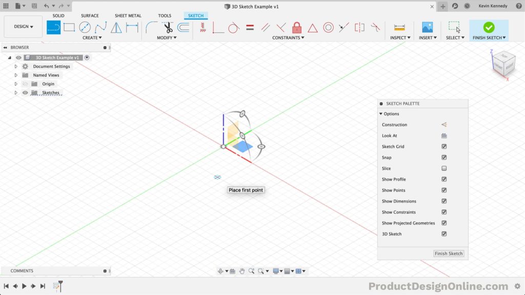
With these enhancements, you now immediately see origin axes, planes, and rotational manipulators to help create your 3D sketch.
Moving from one sketch plane to another is as easy as moving your mouse cursor in the direction you want to sketch. Guidelines then appear to help you understand where the sketch is going to be in 3D space.
Differences Between 2D and 3D Sketching
In a 2D Sketch, we constrain sketch geometry to the plane used to create the sketch. You can create a new 2D sketch on each of the following:
- XY, YZ, or XZ origin planes
- Faces
- Construction planes
A 2D sketch plane can originate anywhere in 3D space. However, the selected plane restricts sketch geometry to that plane.
With a 3D sketch, Fusion 360 removes the planar restriction allowing you to create sketch geometry anywhere in 3D space.
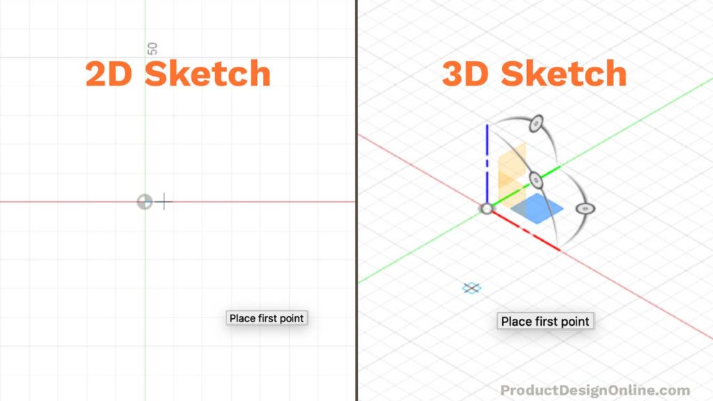
It’s important to note that 2D sketches also exists as an individual Sketch feature in the parametric timeline. You’ll often have several different sketch features that make up a design.
Contrary, 3D sketches will be one single sketch feature in the timeline.
Sketch dimensions and constraints can sometimes be harder to update and manage with 3D sketches – making the concept of design intent harder.
Knowing when to use a 3D sketch instead of a 2D sketch can make all the difference.
When to Use 3D Sketches
There’s no question that 3D sketches come with extra complexity. That may have you wondering, “When should I use a 3D Sketch?”
In short, use a 3D sketch to create a path for tubing, sweeps, lofts, or surface edges, when the design continues to multiple planes.
Use a 2D Sketch to create planar (flat) sketch geometry for common features like extrude and revolve.
3D Sketches are also good for:
- Routing
- Sweep Path
- Guide Curve
- Surface Extrudes
- Curve-Driven Patterns
- Split (Body) Lines
- Assembly skeletons
In summary, use a 3D sketch if it will save time creating the model when compared to using traditional planes and 2D Sketches.
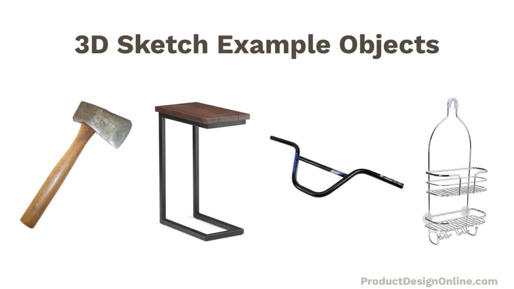
3D sketch example objects:
- Bike handlebars
- Shower caddy
- Axe head
- Furniture with continuous shapes
Create a 3D Sketch in Fusion 360
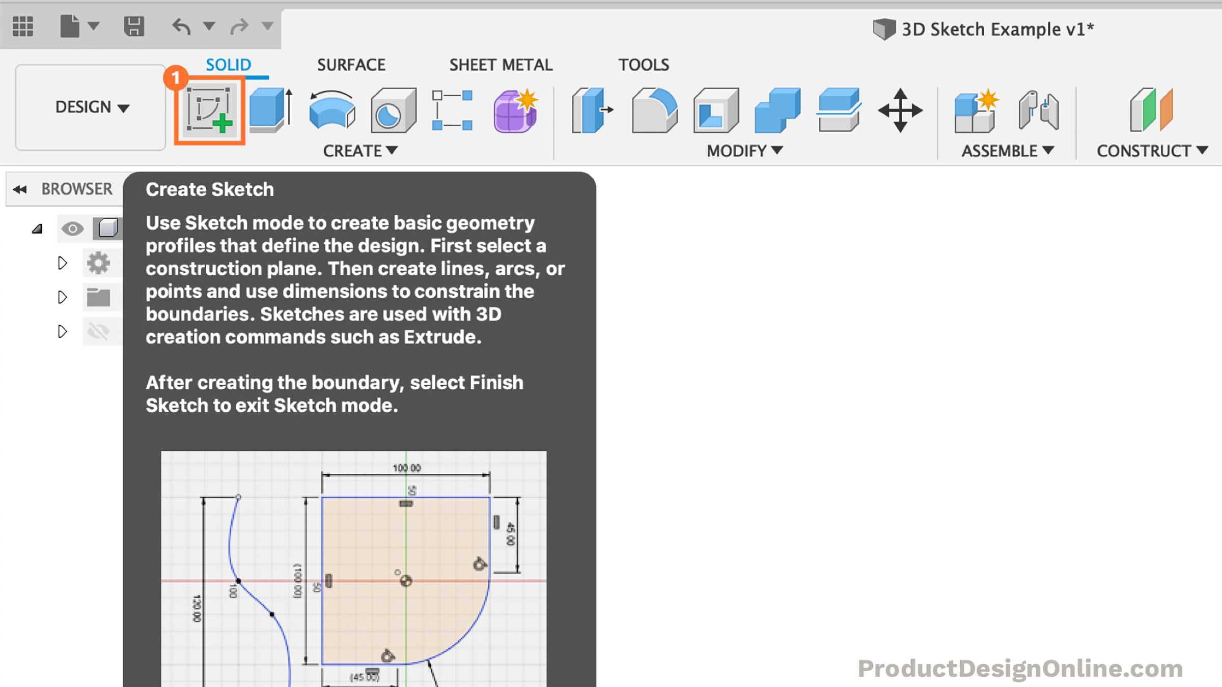
- Select the Solid tab in the Design workspace. Select Create Sketch in the toolbar.
- Select the initial plane or face to begin the sketch on.
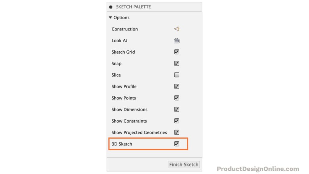
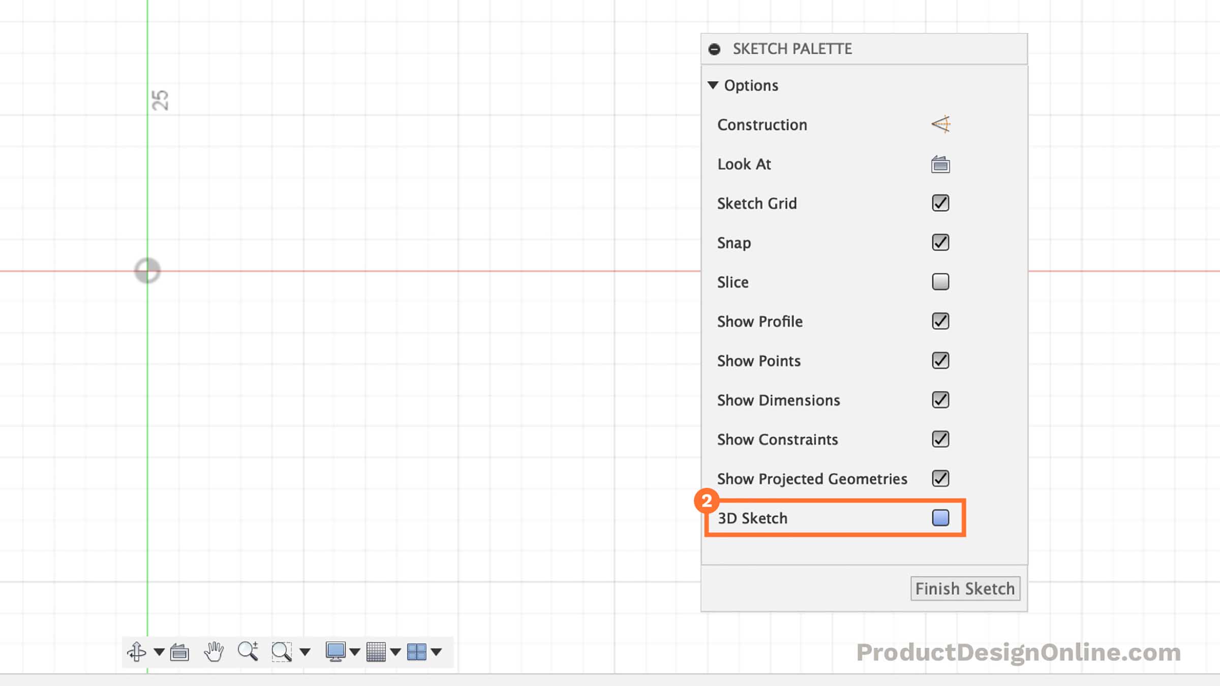
- Check the 3D Sketch box in the Sketch Palette.
- Select one of the sketch commands supported by 3D Sketch. The 3D Sketch Manipulator will appear at the default location (0,0,0).
- Select a sketch plane or adjust the 3D Sketch Manipulator. If desired, switch to a different sketch plane by selecting it (XY, YZ, or XZ) or rotate the sketch plane by dragging any rotation handle.
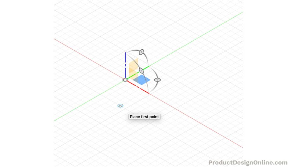
- Click anywhere on the active sketch plane to create the first sketch point. Hover along the axis until its extension line displays, then click to place the point to restrict the point along an axis.
- Continue to place sketch points as desired. The origin of the 3D Sketch Manipulator will shift to the last point you placed, as you place 3D sketch points.
- Click Finish Sketch in the toolbar to stop the sketch.
Practice 3D Sketch – Sweep a Side Table
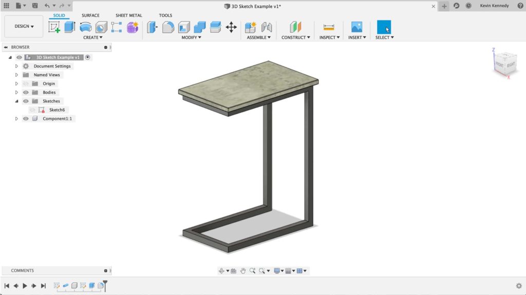
Time needed: 20 minutes
I happened to come across this “C Side Table” on Amazon and thought it was the perfect 3D Sketch beginner project.
This table design could theoretically use 2D Sketches. However, we can make the table much faster using 3D sketches.
- Select Create Sketch in the toolbar
Start the sketch by selecting the XY origin plane. We’ll click this plane to start by drawing the bottom of the table as if it were sitting on the ground.
- Turn on 3D Sketch
Select the 3D Sketch checkbox in the Sketch Palette to turn it on.
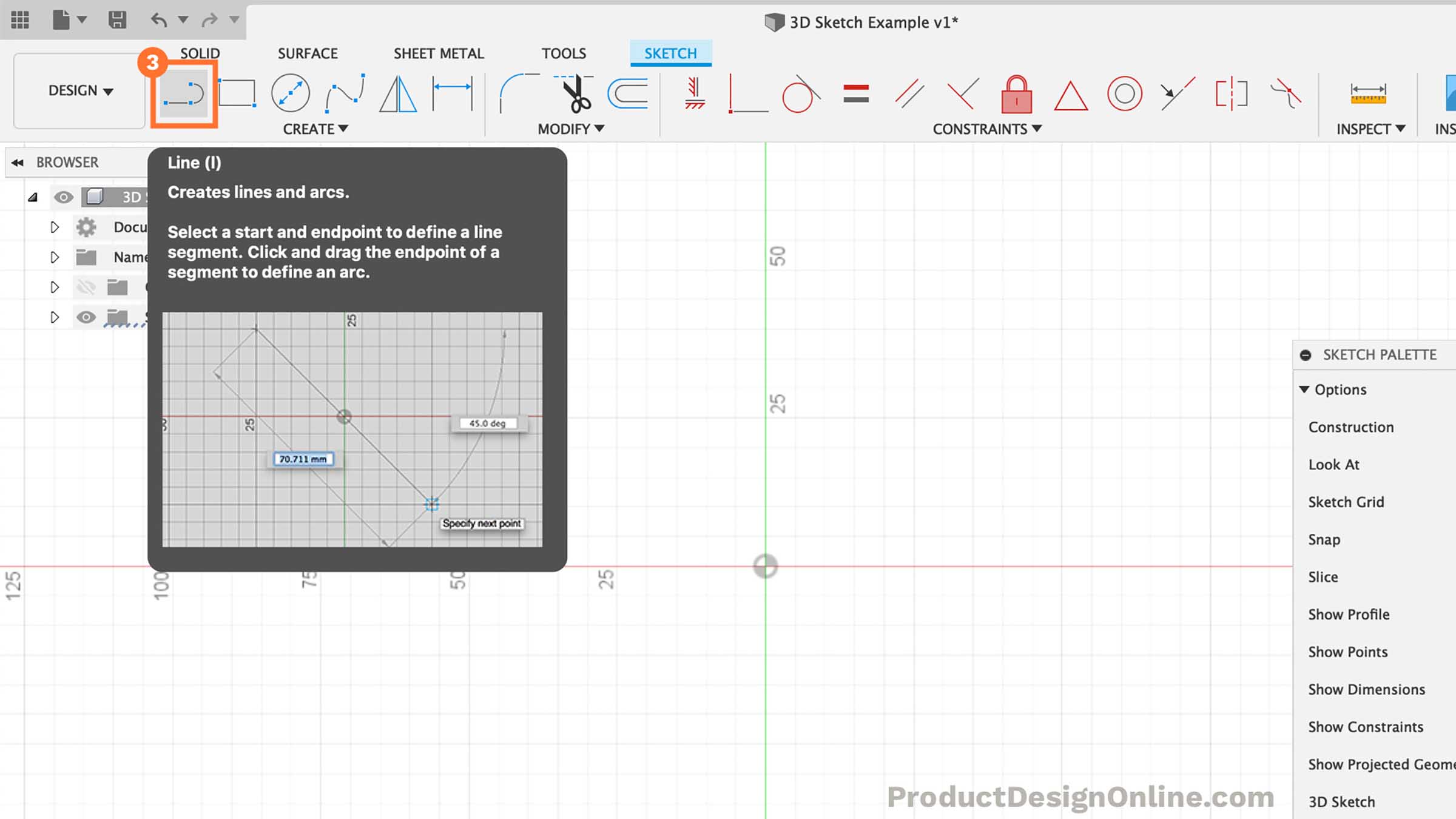
- Activate Line & Home View
Select the line feature in the toolbar or hit the keyboard shortcut “L.” Select the “Home” position next to the ViewCube. This will help us sketch in 3-dimensions.
- Draw First Line from Origin
At this point, we can start the line by setting the first point at the origin point.
Similar to a 2D sketch, we will drag our mouse cursor along the green Y-axis. Type out 45cm for the length and then click where the line snaps into the Y-axis. Fusion 360 will automatically add a “horizontal/vertical” constraint for us.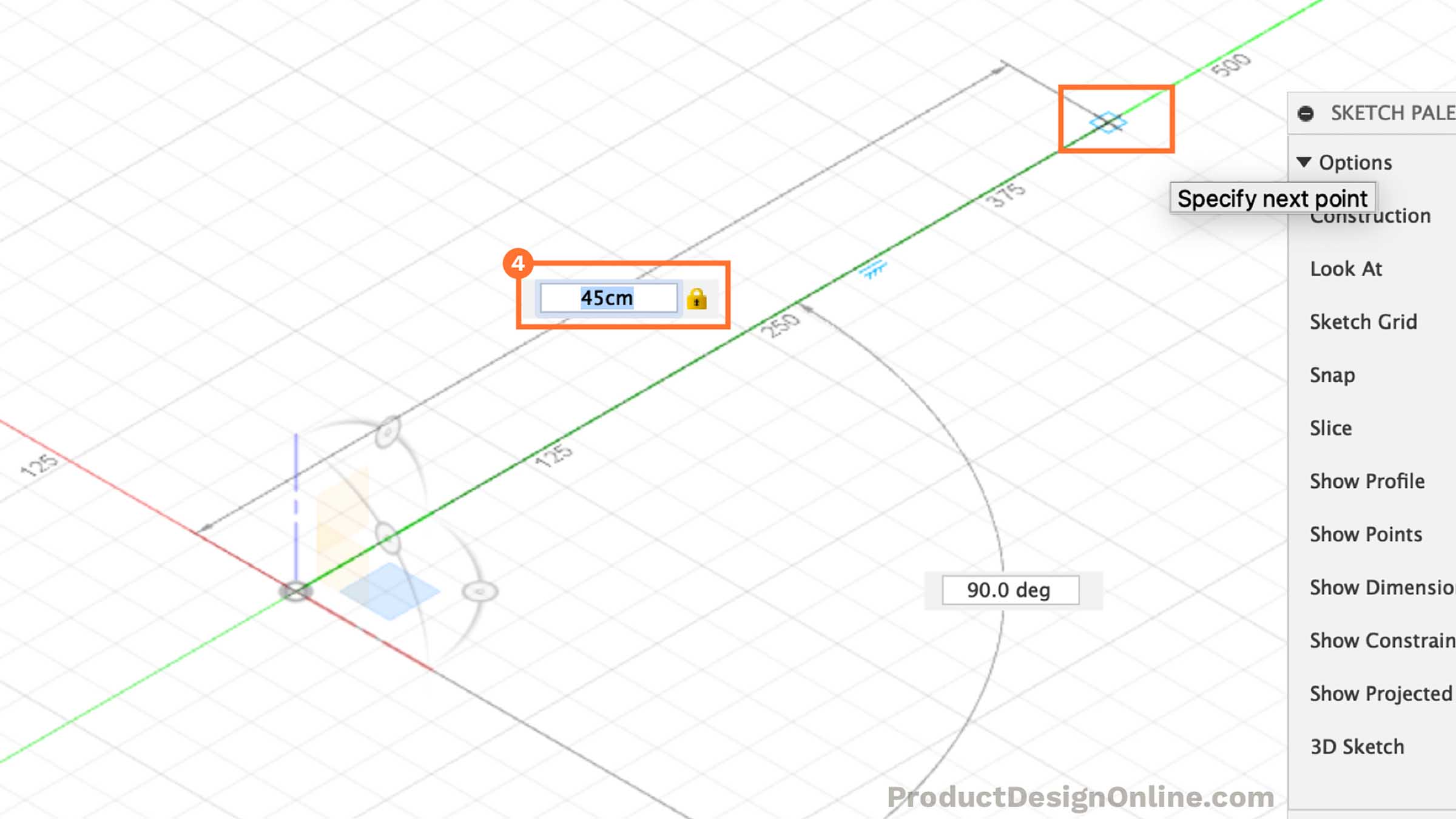
- Draw Line Straight Up
We can start to sketch the height of the table by moving our mouse cursor to the blue z-axis. The cursor should snap to the z-axis when close.
Type out 60cm for the height. Carefully select the blue z-axis to set the line, making sure it automatically add a vertical constraint.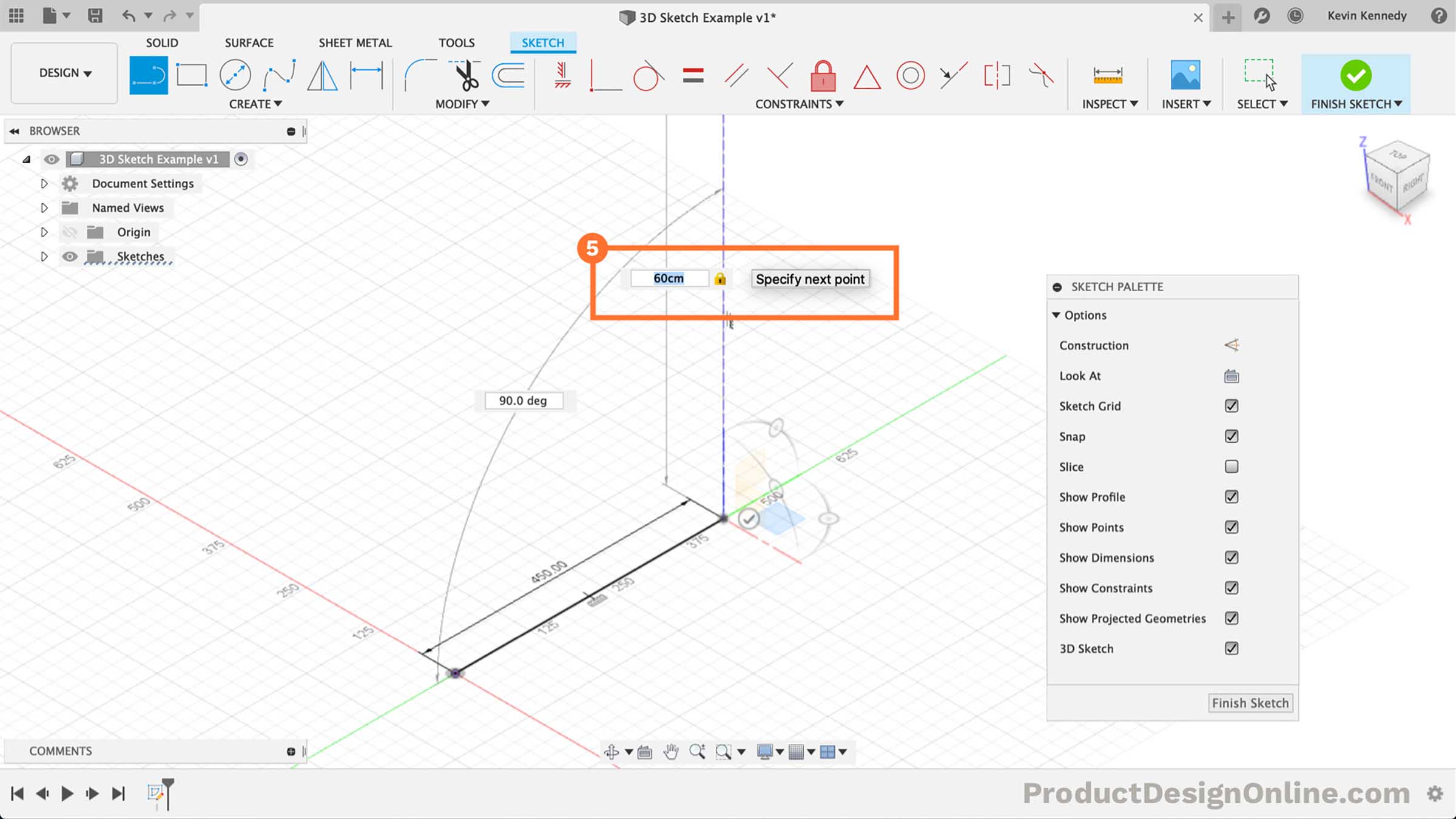
- Heading Back Toward Center
For the third line, we’ll want to head back toward the center, while following the green y-axis. If you haven’t already noticed, see that the origin planes move to the end of our line while in 3D sketch mode.
This is where things start to get tricky with 3D Sketches. We don’t want to overuse sketch dimensions. Instead of typing out a dimension, click to place the line along the y-axis.
Shift-click the endpoints of the line we just placed and the origin point or the original starting point of our first line. Select the “horizontal/vertical” constraint in the toolbar. This will ensure they stay the same length while making it easy for us to update only one dimension.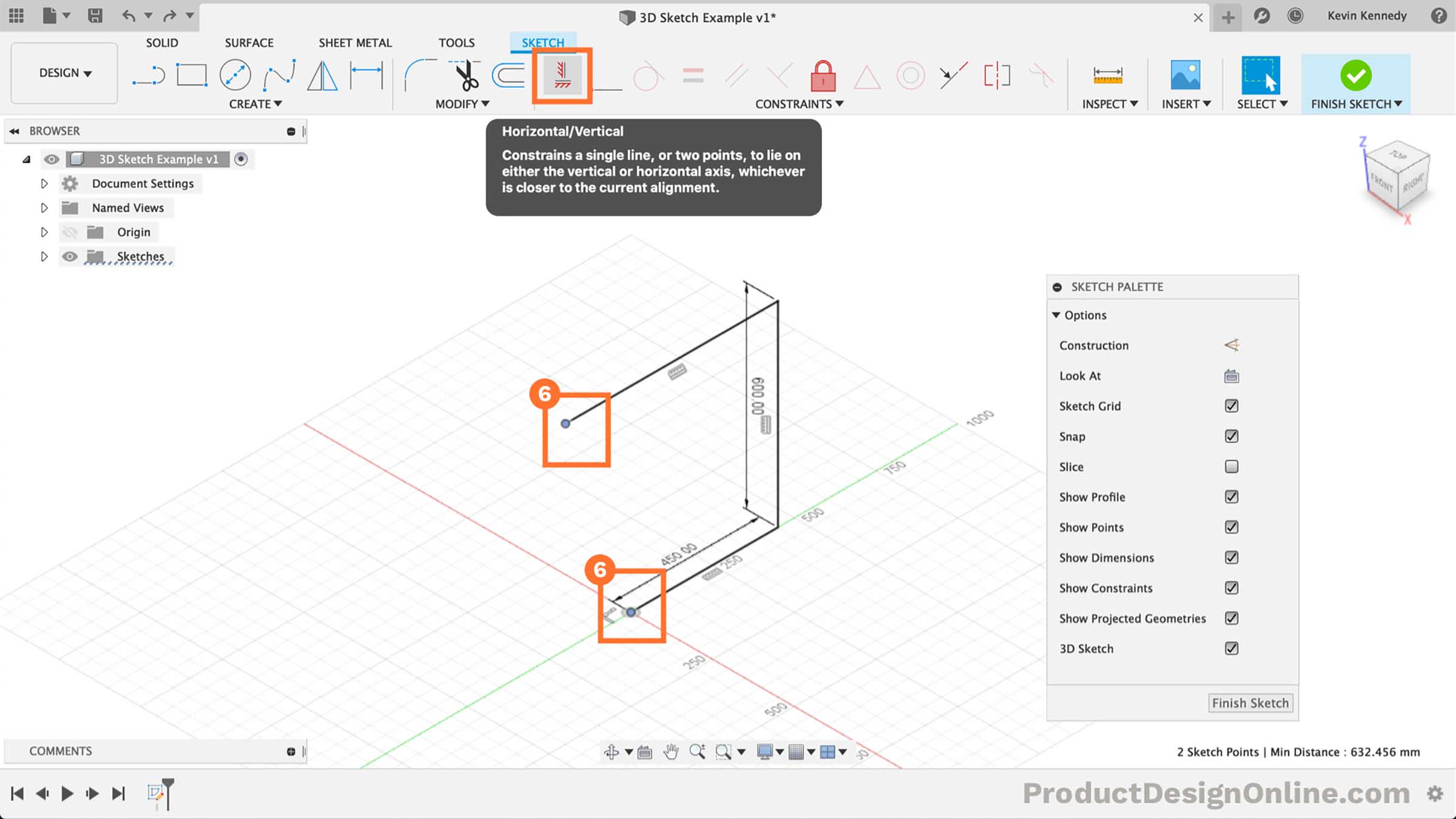
- Reactivate Line Command
Select the line feature in the toolbar. Select the endpoint of the line we just placed.
The 3D sketch planes and manipulators will reappear once you select the endpoint.
For this line, we’ll type out 25cm for the width. Make sure to snap the line in place along the red x-axis.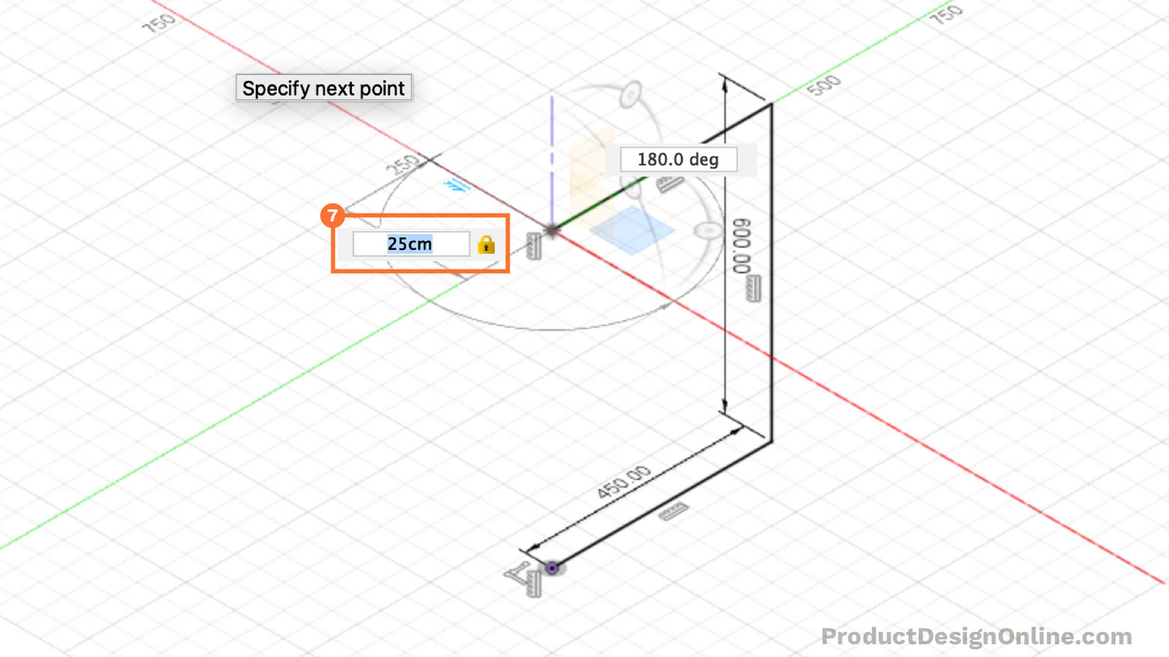
- Heading Back to the Right
We’ll now want to create a line heading back to the right.
Since we’ve already defined our length, we’ll want to use sketch constraints instead of sketch dimensions for this one. Click along the green y-axis where the line snaps in at the same length of the opposite line.
Hit the “Escape” key on your keyboard. Shift-click the endpoint of this line and the opposite line. Select the “Horizontal/Vertical” Constraint in the toolbar. This will force the line to stay the same length.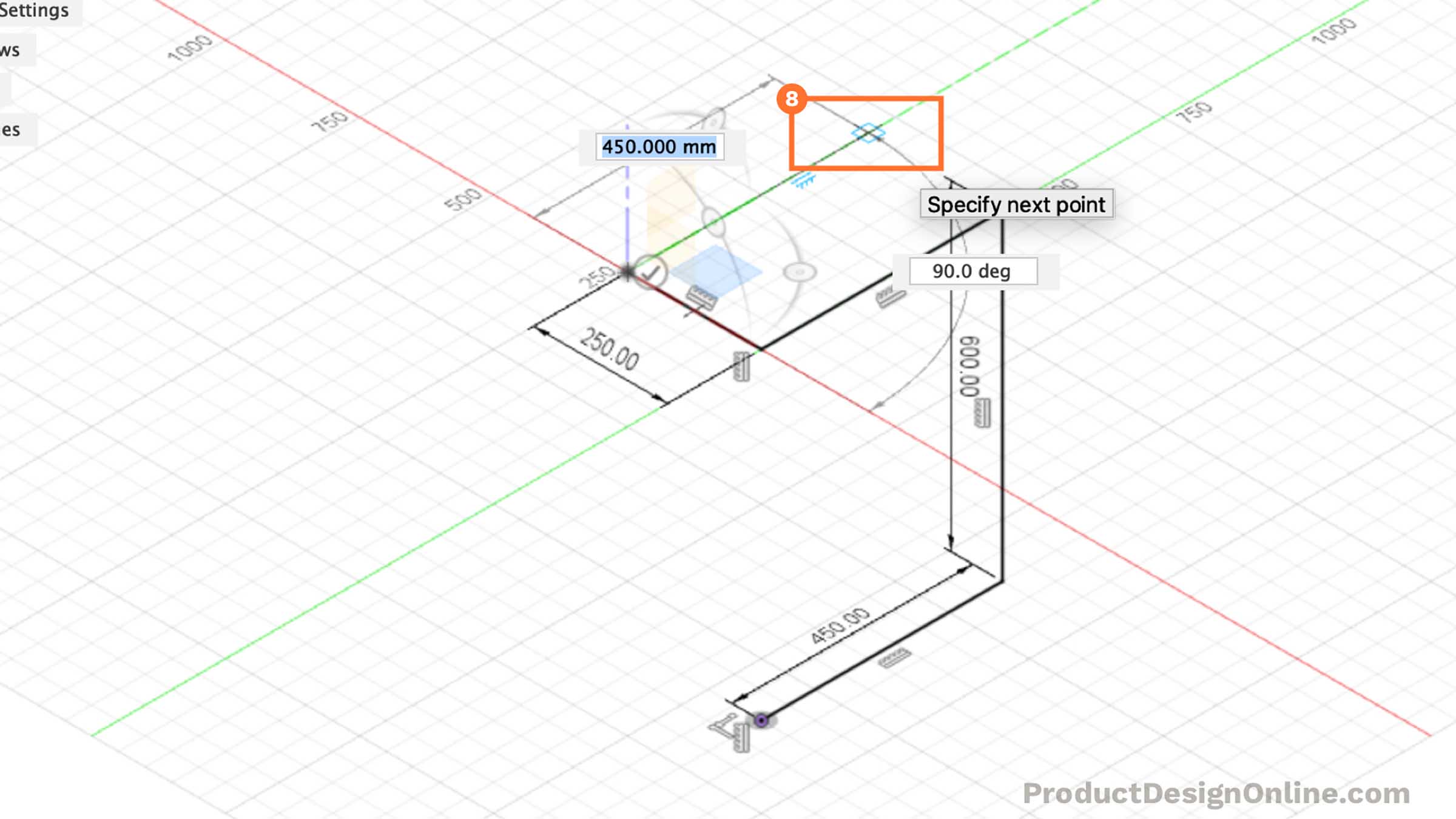
- Heading Straight Down
Reactivate the line command in the toolbar. Select the endpoint of the last line we created.
Heading straight down, click to place the line along the blue z-axis where it snaps equidistant to the opposite line. The line should be 60cm.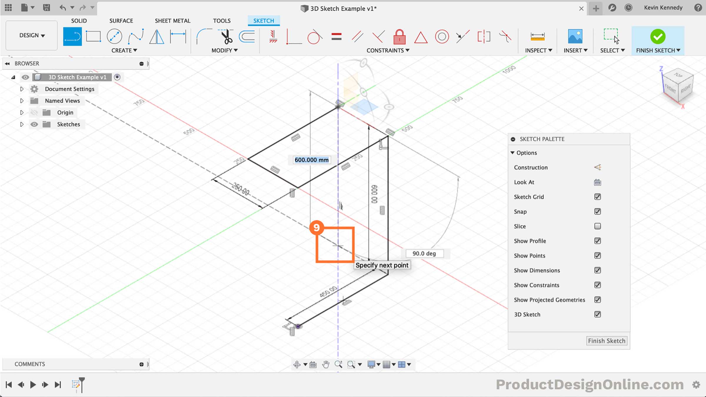
- Finishing off The Lines
Let’s finish off the lines by mimicking the “C” shape on the opposite side.
Place the first endpoint at the red y-axis. Create the second line by clicking the origin point.
Hit the “escape” key to clear the line command.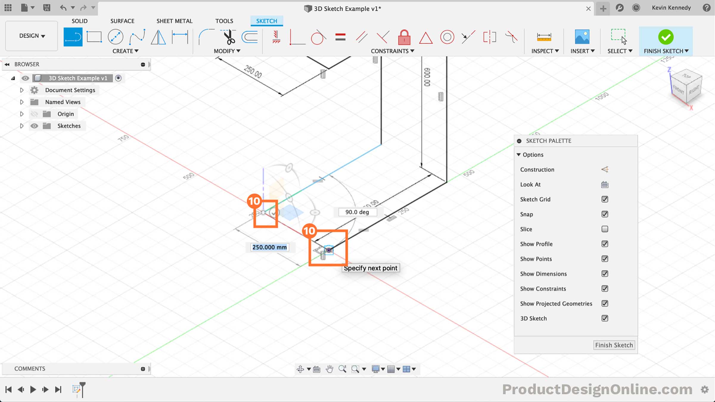
- Adding the Final Constraints
To ensure our sketch is fully-constrained, we’ll need to add the final constraints.
It appears the last line created does not have a constraint forcing it to remain in one direction. Simply select the line and then select the “Horizontal/Vertical” constraint in the toolbar.
Our sketch is now fully-constrained. We can double-check this by looking for the red lock icon next to the Sketch name in the Browser.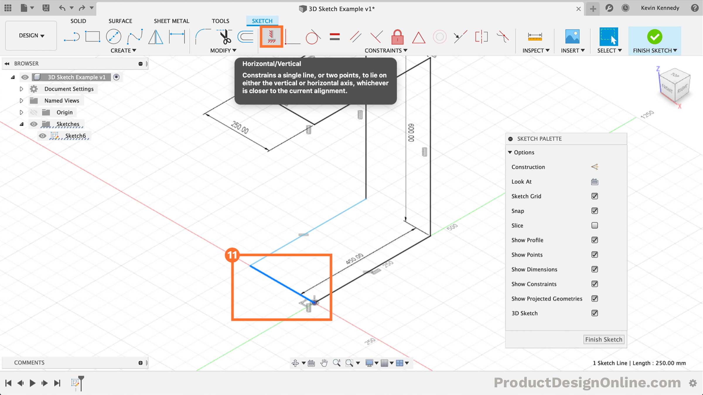
- Turning the Sketch into Pipes
Our sketch is now complete. We’re ready to use the Pipe command to turn the sketch into furniture.
Select the Solid tab in the toolbar. Select Pipe from the Create dropdown. Select the 3D sketch geometry.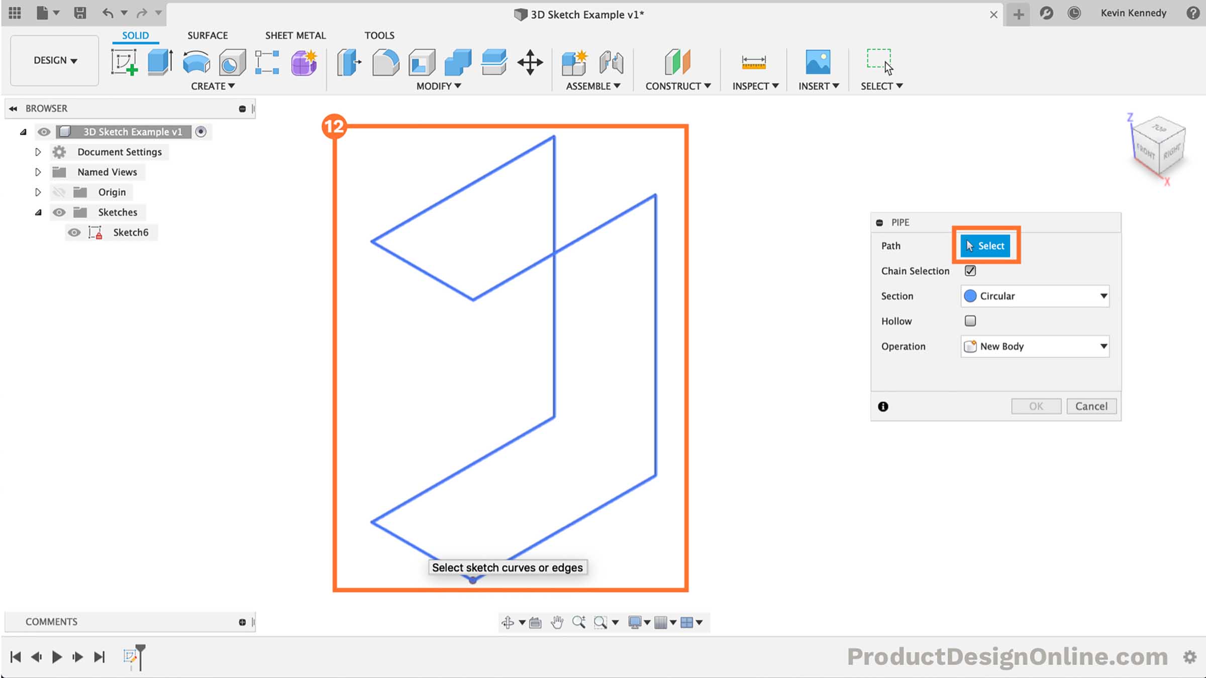
- Adjusting the Pipe Features
We’ll want to set the Section type to Square. We can also change the thickness of the pipe by changing the section size.
I’ve entered 2.5cm for the section size.
Select the “Hollow” checkbox, which displays the section thickness. For the section thickness type out 2mm.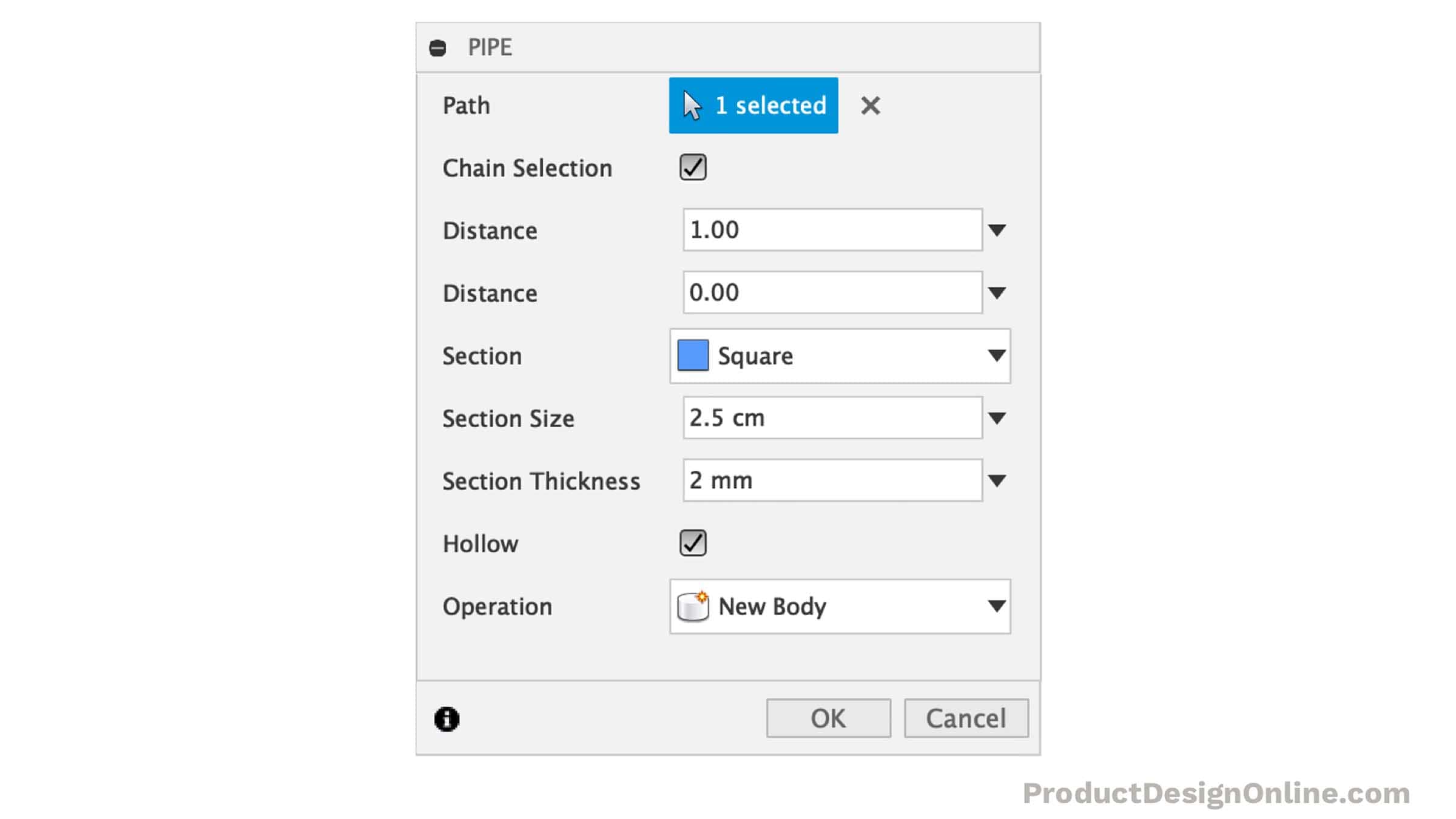
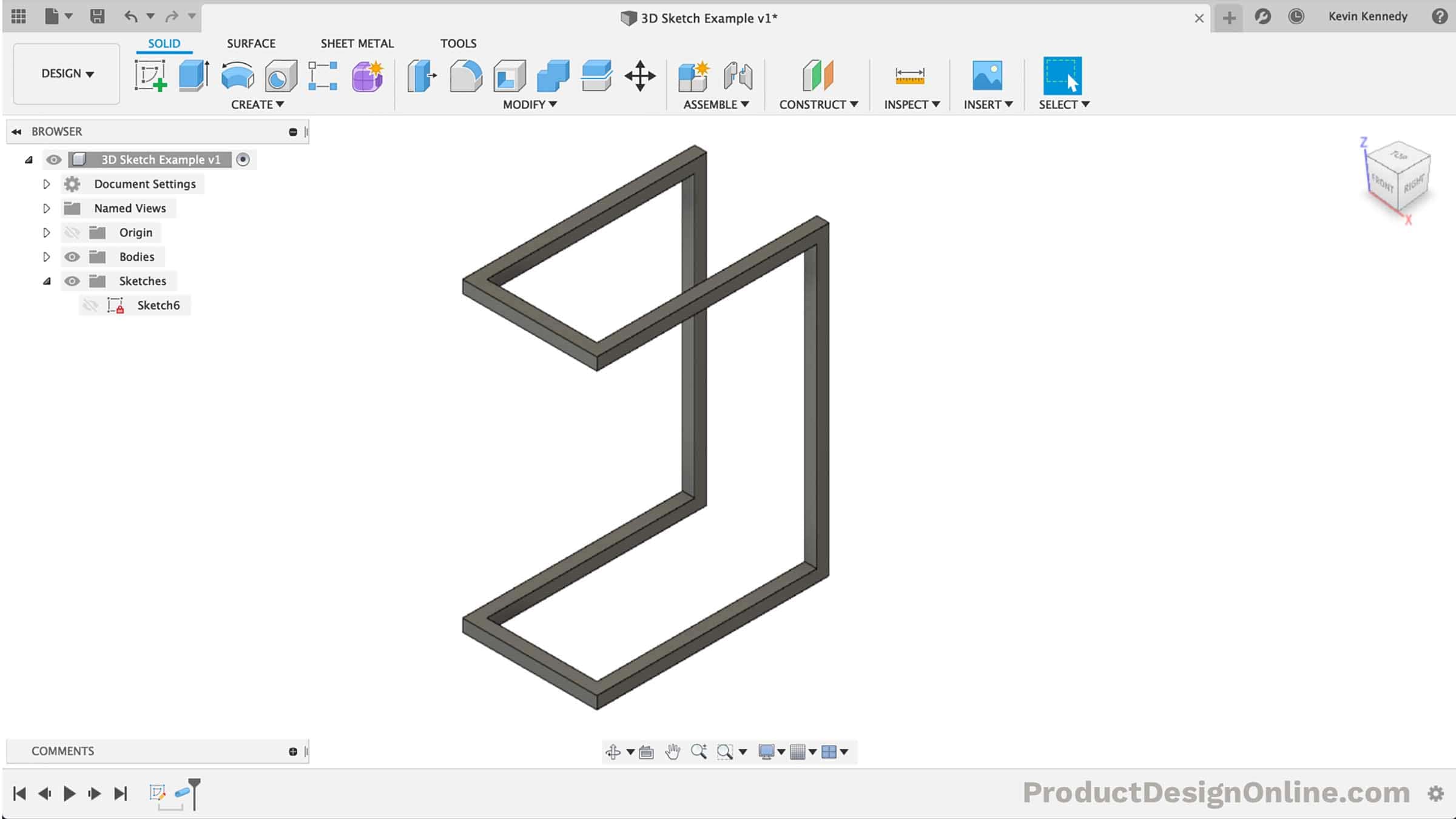
- Congrats and Next Steps
You’ve now completed the 3D Sketch! Finish off the model by adding boards to the top – or whatever surface you desire!
Kevin’s on a mission – making CAD education accessible. If you’ve been learning with PDO’s free content, consider donating to help Kevin continue to create learning resources for everyone.
Support PDO – Get Demo Files
Given the lack of a printed user guide or detailed manual for Fusion 360, I’m wondering Kevin why don’t you write one. Especially with your thorough knowledge and experience. I’d be willing to invest in such a guide. Please think about it.
Hi Anthony,
That is something that I’ve thought about before. My only concern is the amount of time it would take. As of now, I do all of the YouTube videos, answer questions and comments, this website content, etc… outside of my full-time work. Most weeks I don’t necessarily get to creating all of the content I would like to.
In the future, this is something I will certainly consider, once I get some of the courses done that I’m working on.
Thanks for your support!
Cheers,
Kevin
Hi Kevin. Love your videos and the tutorial on the recent upgrade to 3D Sketch. Their is just one problem. The 3D Sketch is not working in the latest version that I have recently received. Could that be a problem for hobbyists. Thanks mate. Keep up the good work.
Hi Phil,
Glad to hear you’re enjoying my tutorials!
As far as the 3D sketch not working, have you tried turning the 3D sketch preference on and off? I’m referring to the actual user preference and not the option in the Sketch Palette. Select your Username > Preferences > Design (tab on left of dialog) > Uncheck and then recheck the setting “Allow 3D sketching of lines and splines” > Apply > OK.
After doing that try 3D sketching again. You’ll also need to make sure thee “3D Sketch” option is turned on in your Sketch Palette.
Let me know if that fixes it for you.
Cheers,
Kevin
Hi Kevin, your guidelines and tips are veeery useful! Thank you! I have question regarding symmetry constrain in 3D sketching. I want to draw bike handlebar in 3D sketch and symmetry constrain would be useful. However, when I shift a point out od sketch plane, the symmetry constrain does not work, becasue it was set with a symmetry line in the 2D sketch. So I guess now the symmetry constrain should be set to a plane instead of a line. Is there any possibility to do it in Fusion 360?
Hi TB,
Glad to hear you’re enjoying the lessons!
There is no way to apply constraints to modeling objects, such as construction planes. The constraints can only be used in the sketch realm. At this time, constraints can be a challenge with 3D sketches – I believe that is something on the F360 team’s roadmap to improve.
What I would suggest instead – Focus on only 1 half of the design. Then, once you’ve modeled it you can use the modeling mirror command to create the other half, ensuring it is symmetrical.
Cheers,
Kevin
Hi Kevin. Love your videos and the tutorial on the recent upgrade to 3D Sketch. Can you help in a sum as i am having alot of problem solving it. Pls contact me on this email MANAV.PAREKH35@nmims.edu.in so that i can send you that sum
Thanks for your time !!!
Hi Manav,
Glad to hear you’re enjoying the tutorials!
Please join the PDO Community and ask your questions in the Fusion 360 Q&A space.
This ensures other folks can learn from the questions and many times the community is able to chime in with answers before I’m able to respond.
Cheers,
Kevin
Hi Kevin, I am trying to draw the top of a WigWam i.e. 3 tubes at 120 degrees apart meeting at 30 degrees to the vertical. I have tried in 2D and 3D but cant get the geometry right and the Tube command will only work for 2 out of the 3 tubes! Can you help me to create this shape with a nice rounded top please?
Hi Paul,
The Pipe (tube) command is fairly limited relative to the Sweep or Loft commands. I would suggest trying it with the Sweep command first so you have full control over the shape. Loft may be required if you need extra control where things bend and/or meet at the middle.
Cheers,
Kevin
Hi Kevin,
I have been using Fusion 360 for a little while now and can’t seem to learn how to make the hand go away when using 2D sketches. When I draw lines, instead of the crosshair, sometimes a hand pops up and says click to select sketch plane. This is very annoying.
Hi Corey,
Can you make sure that the ‘3D Sketch’ option is unchecked in your Sketch Palette? You may have to restart Fusion 360 after turning 3D sketch off. Generally, restarting is not required, but may be worth it to validate if it is this setting at play.
Best Regards,
Kevin