By the end of this video, you’ll know how to wrap text around a curve or cylinder in Fusion 360. I’ll show you three different examples and use cases.
Unfortunately, Fusion 360 does not offer a simple native way to wrap text on a curve. I will show you some different approaches that you can take as a workaround. You’ll then be able to decide which option works best for creating the text on your curved surface or cylinder.
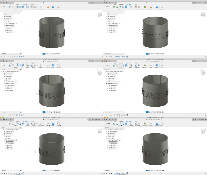
Creating Text on a Cylinder

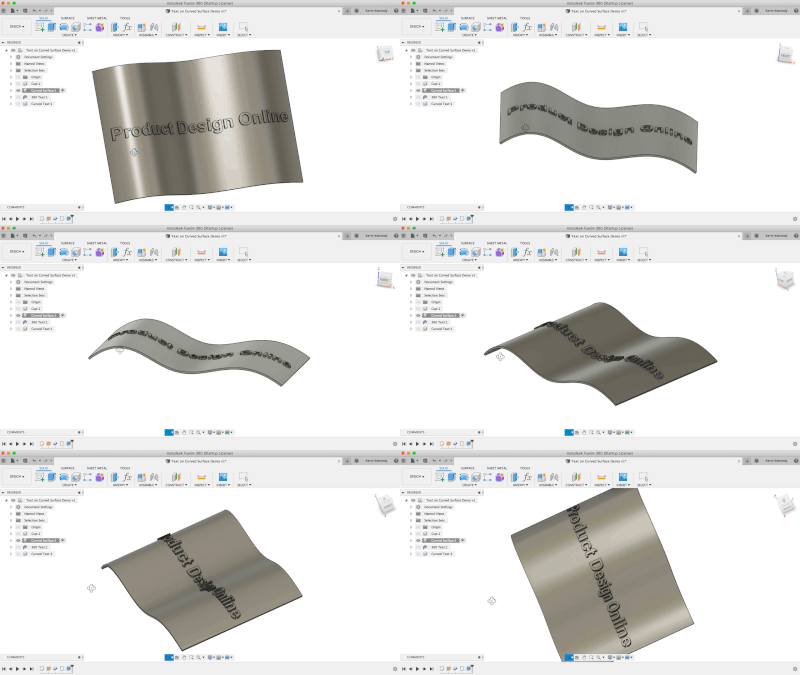
Creating Text on a Curved Surface

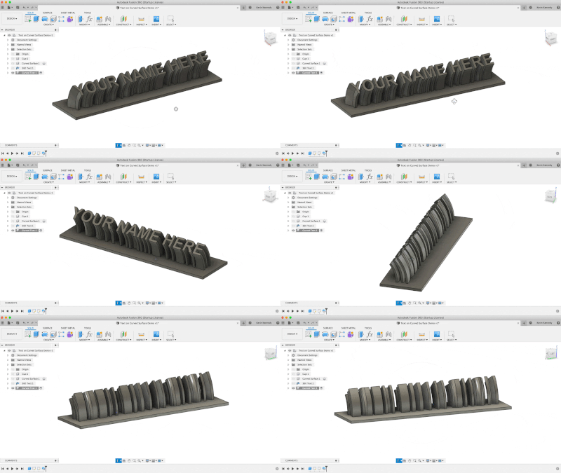
Sweeping Text into 3-Dimensions

Learn the Text Command
In this tutorial, I walk you through all the options that are available in Fusion 360’s text command.
I’ll discuss how to create the text, change the font, and change the size. I’ll also show you how to “explode” the text, which turns the text into Fusion 360’s native sketch geometry. Exploding text is a necessary step if you want to extrude certain typefaces.
Transcript:
By the end of this video, you’ll know how to wrap text around a curve or cylinder in Fusion 360. I’ll show you three different examples and use cases. This tutorial was requested by several subscribers. If you have a tutorial idea or if there’s something that you can’t figure out how to do then comment your ideas down below. I can’t promise I’ll be able to make a video for everything, but I always make videos for at least the topics with a lot of interest.
For the first example, I have this cup and I want to place the text around the outer face of the cylinder. Where the text is embossed or debossed. This is a common use case that a handful of users have asked me about.
I’m going to create a new sketch off of the XZ origin plane. Then, I’ll activate the text tool from the “Create” dropdown list.
I’m going to click with my mouse to place the text anchor point and I’ll type out “KEVIN” for the text.
Because I want the focus of this tutorial to remain on some different ways to get the text on curved surfaces, I’m not going to cover all of these options in the text dialog. I do have another video that covers that and you can find that, along with some additional resources, at ProductDesignOnline.com/19… that’s ProductDesignOnline.com/19 [one – nine].
For now, I’m just going to increase the size to about 20mm and I’ll reposition the text so it appears to be centered on the cup. After clicking “OK,” you’ll see we have our text in the middle of the cup.
I’ll activate the extrude command with the keyboard shortcut letter “E” as in Echo. I’ll select the text and I’ll extrude this text out, running through the cup.
It defaulted to the “cut” operation, as it’s running through the body, so I’ll change the operation to “new body” so we can see the text.
I’ve seen some users extrude the text out like this and then they create another cylinder and use the split body command to cut the shape out or they draw another circle on top and extrude cut the text. Those methods are feasible, however, there is a simpler way to achieve similar results.
What we want to do instead is to change our “start” operation. I’m first going to get rid of the distance so that’s not in the way. Then, I’ll change the “start” operation to the “from object” selection.
You’ll see that gives us the option to select an object. This is where you’ll want to select the face that you want the text to be on. In our case, we want this to be on the outside of this cup, so I’ll select the outer face of the cylinder.
Note that nothing happens at first because we haven’t yet applied our thickness or the extrude distance. I’m going to type out 2mm in the distance dialog. Depending on how the extrude command selected your face, you may have to add the minus symbol in front of your distance, to get the text to be embossed.
I’ll click the “OK” button so we can take a look at the results. You’ll see in just a few simple steps this does a pretty good job of embossing the text on our cup. If you want to deboss the text then you would simply need to flip the distance in the opposite direction, by adding or removing the minus symbol.
However, there are two issues with this method. First, you’ll see that the letters are slanted based on the curvature of the cup. In some scenarios, you may be looking to have the text coming straight out.
The second issue is that this method only works within the boundary of the width of the object in any single direction. If I wanted the text to wrap around the cup then we could do this method a couple of times, using separate features. However, there is another method that we could use, which I’ll show you in just a bit.
First, I want to show you this same method used with a curved surface.
I’m just going to hide the cup component and I’ll show the Curved surface component that I created for this demo. I have a spline that was extruded and thickened with the surfacing tools.
I’ll create a new sketch off of the XY origin plane. Using the shortcuts box, I’ll activate the “Text” command.
I’m going to type out “Product Design Online” and I’ll make the text 18mm and I’ll bold the text. I’ll position this so it appears to be centered and I’ll click “OK”.
Once again, I’ll activate the extrude command with the keyboard shortcut letter “E”, as in echo.
We’ll have to change the start direction to “From Object” and select the surface. Then, I’ll type out 2mm for the extrude distance.
We now have a similar result as the cylinder example, I just wanted to point out that this method does work on geometry other than cylinders.
Keep in mind that you may even run into a scenario where you need the text to follow a certain path or curve, without the background surface. You can always hide the background surface, you’ll just need to make sure that your extrude operation is set to “new body” instead of “join”.
Let’s now take a look at the other method of getting text to wrap all the way around a cylinder.
For this method, we’re going to use one of the tools in the sheet metal tab. We’ll start off by creating the cylinder and then we’ll “unfold” the part. After the part is unfolded we’re then able to create the text or make any edits in a flat state.
I’m going to create a new component for this example, which I’ll name “360 Text.”
Because we’re going to use a sheet metal feature we’ll need to select the “sheet metal” component option. Sheet metal components require a sheet metal rule to be applied. We can simply leave this to the default of steel, but note that you would want your rule to match your desired thickness of the cylinder.
At this point, we’ll need to sketch out a circle. I’ll use the keyboard shortcut letter “C,” as in Charlie, to activate the center-circle command.
I’m then going to create this on the XY origin plane off the center origin point.
I’ll make the circle 100mm in size.
I’ll select the sheet metal tab in the toolbar, so I can activate the flange tool. With the flange tool active, you’ll see that as I select the circle, it turns it into the thickness of our material, or whatever the sheet metal rule is set to. We don’t have an option for the direction of the flange because we have a closed profile shape.
The key takeaway here is that we’re going to need a shape that isn’t completely closed.
I’m going to undo the previous steps. We can either cut a notch out of the circle, or we can always use the “Center Point Arc” command to create an arc set to 359 degrees. In other words, as close to a circle as we can get without closing it.
I’m going to use the “Center Point Arc” and I’ll type out 359 degrees, so we just about have a closed circle.
I’ll also click on the original circle and hit the delete key on my keyboard, as we no longer need that.
We can also apply a radius sketch dimension to the arc. I’ll set the radius to 50mm, so it’s the same as our original circle.
I’ll now reactivate the flange tool from the sheet metal tab.
Watch what happens as I now select the arc. Because this isn’t a closed profile shape, we’re able to extrude this to the desired distance, using the same flange tool.
I’ll type out 100mm, so it’s similar in size to the first example.
If you’re not familiar with the sheet metal tools, then you’ll want to know that the thickness is defined by your sheet metal rules, or in our case the default of steel.
I’ll go ahead and click “OK” to create the flange, so we can add text to it.
We can now use the “unfold” feature, which is under the modify dropdown list. It’s really important to know that the unfold feature is different than the “Create Flat Pattern” feature. The “Creating a Flat Pattern” does also allows one to make edits in the flat state. Although, those edits are not translated back to the 3D model as they are with the unfold feature.
After activating the unfold feature, I’ll try to click on the object as our stationary entity, but as you’ll see, we’re not allowed to select a curved surface. We need a flat surface to satisfy the stationary entity.
I’ll hit cancel for now. Then, I’m going to select the end face of this flange and I’ll hit the keyboard letter “E” for extrude. I’m going to extrude this out .5mm, making sure that the operation is set to “Join” before clicking “OK”.
I’ll now activate the “unfold” feature once again. We simply need to select either of the side faces and then we can select the cylinder or select unfold all bends, as we’ll end up with the same result.
You can now create the text, or your SVG logo, or even a pattern on this flat surface, and then we’ll be able to refold the part back to a cylinder.
You’ll want to make sure that you sketch on the correct surface of the cylinder, depending on whether you want the text to be on the outside or inside.
To double-check this, you can click the “refold” feature in the toolbar.
After the object is refolded, we’ll have both the unfold and refold features in the timeline below, and we can slide them back and forth.
I’ll leave the timeline marker set to before the refold feature so I can add some text, while it’s in the flat state.
I’m going to right-click on the face of the flange, and I’ll select “Create Sketch”.
Then, I’ll activate the text tool so I can create some text that runs from edge to edge across the flange. I’m going to position this so it’s about in the middle.
I’m going to extrude the text out 2mm, making sure to select the “join” operation, so the text and flange are one single body.
I’ll drag the timeline marker back to the end, and just like that, we have text that wraps all the way around a cylinder.
We can also select the inside face of our cutout and hit the keyboard shortcut letter “Q,” as in Quebec, to activate the press pull command. Then, I’ll just drag the single directional arrow over another .5mm, to close off the cylinder.
Unfortunately, Fusion 360 doesn’t have this curved text capability built into the native text command. Hopefully, it is something that they can implement in the future.
If you’d like to see this implemented in the future then comment the words “Text on Curve” down below in the comments!
Also, while you’re at it, click that like button if you’re learning something in this tutorial.
The final example that I want to show you is how to make some curved text, or 3-dimensional text that follows a path.
To do this, I’m going to create a new component, for the Curved Text.
Let’s create a box off of the XY origin plane, to create the base of a nameplate. I’ll make the box 200mm in length, 50mm in width, and 3mm in height or thickness.
I’ll activate the text command so we can sketch some text on top.
I’ll adjust the text so that it takes up the majority of the base plate and then I’ll click “OK”.
I’m going to use the sweep command, so I’ll need to set up a path for the sweep to follow.
I’ll activate the 3-point arc command, and I’m going to sketch this on the YZ origin plane. I’ll start from the right corner of the base plate, making sure it snaps to the edge. I’m just going to create an arc, as we can also adjust the shape within the sweep command.
Now that the arc has been created we can use the solid modeling sweep command.
I’ll look at this from the home position so you can see what I’m selecting.
For the sweep “Profile” we’ll need to select our text.
Then, for the sweep “Path” we’ll select that reference arc that we just created. Just like that in a few simple steps, you’ll see that our text is swept along the path and you have a neat little nameplate that you could 3D print.
You can even adjust the length or position of the sweep, making it a bit more angled so there is no need for 3D printed support.
Last but not least, I want to give a shoutout Doug Sanders for supporting all of the Fusion 360 content that I make!
If you have found my tutorials to be helpful in any way then consider supporting by becoming a Patron or making a one-time donation on my “Buy me a Coffee” page. All of the contributions help me keep the website up and running and will help me continue to invest in more gear so I can continue to create high-quality tutorials.
As always, I truly appreciate you taking the time to watch this tutorial. Click that thumbs up icon if you learned something in this video.
To be a part of the Product Design Online community, be sure to subscribe and check us out on Patreon by clicking that Patreon logo right now.
Leave a Reply