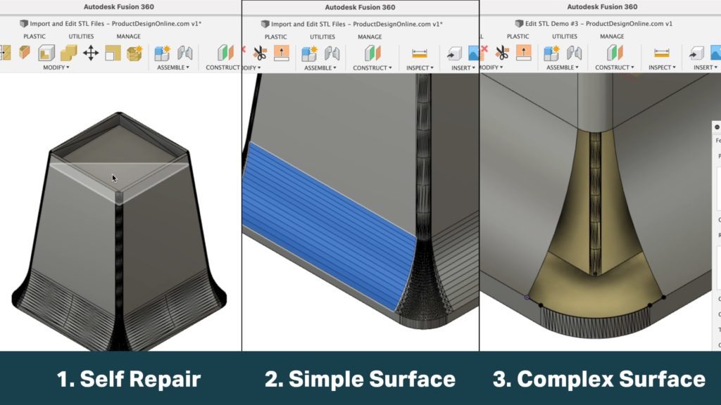
3D printing hobbyists looking to convert STL files to solid BREP bodies can use Fusion 360. This includes the use of Fusion 360’s free Personal Use license. However, it’s important to note that those on the free license will not have access to the Prismatic conversion type.
In short, the Prismatic conversion (released July 2021) will automatically translate most mesh files to a solid body, as if it were created natively in Fusion 360. The largest advantage is that it saves time and effort from having to clean up mesh triangles (i.e. mesh facets) that result from the original Faceted conversion method.
The Faceted conversion method remains free to all license types, including the Fusion 360 Personal Use (“Hobby”) license. Cleaning up the mesh triangles, often referred to as ‘facets,’ can be done directly in Fusion 360. This allows you to add text or alter the dimensions or parts of a model, without having to recreate the model from scratch. That said, there will be times when cleaning up the STL file is not worth it, when compared to recreating the model from scratch in a truly parametric way.
The following tutorial and demo files will help you learn how to import STL mesh files, convert the mesh files to solid BREP bodies, and clean up those pesky mesh triangles.
The techniques outlined below range from beginner to more advanced concepts, all of which are covered in the lesson.
Import STL in Fusion 360
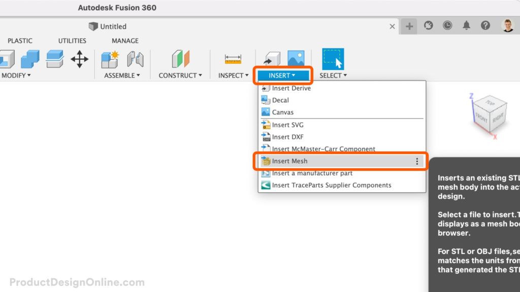
To convert your STL or mesh file in Fusion 360, you will want to insert it via the Insert Mesh command. Always avoid uploading your STL to the Fusion 360 Data Panel, which does not allow you to set the Unit Type or reorient the model.
- In the Solid tab of the Design Workspace, select the Insert Mesh command from the Insert menu.
- A dialog will open. Select the desired mesh file from your local computer > Open.
- Set the Unit Type, Reorient the Model (Flip Up Direction), and Position the model > OK.
Edit and Clean Up STL Files – 3 Workflows
You can use the following three workflows, which are covered in-depth in the video tutorial, to remove and clean up STL mesh triangles. These workflows range from beginner to advanced and results will vary per each individual STL file.
In general, if the model is something that you could create in Fusion 360 (or an equivalent parametric modeling program), then it is possible to remove the mesh triangles. If the model is organic – originally created in a mesh modeling program (Blender, Maya, etc) – then there’s a good chance that this process will not work.
Keep in mind that cleaning up STL mesh triangles is not required in order to have successful 3D prints. A common myth is that the mesh triangles will affect the outcome of the 3D print. However, this is only true if you reduce the number of mesh triangles that make up the shape.
Otherwise, the mesh triangle is simply visual in the editing software (Tip: change your Visual Style to “Shaded” to take a look).
Your goal should be to remove only the necessary mesh triangles to add text or change the size or shape of the model.
Workflow #1: Self-Repair Planar Faces (Beginner)
Select any planar face, followed by the Delete key. Fusion 360 will attempt to self-repair all adjacent planar faces. Most often, this will quickly result in a single planar face. However, note that this approach is not always an option when too many faces are present. In some cases, planar faces may appear to be on the same plane, but they will not self-repair if they are ever-so-slightly off the plane.
Workflow #2: Surface Model Single Curves (Intermediate)
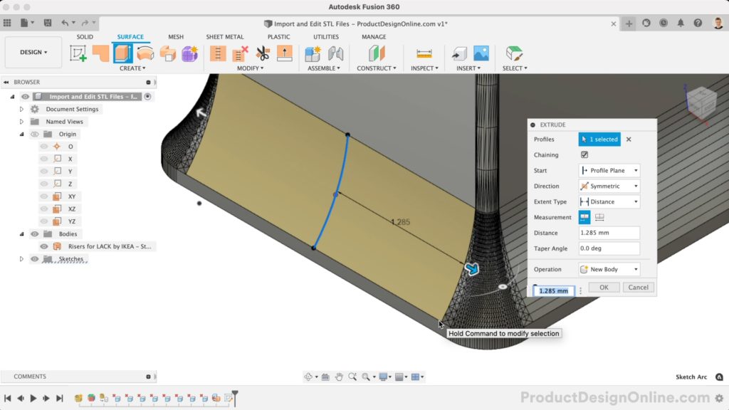
Singular curves can often be recreated quickly using Fusion 360’s surface modeling tools. These tools include the Patch and Extrude commands. In some cases, you may be able to reference existing surfaces, edges, or sketches to quickly recreate the surface. If not, you will want to create reference geometry through the use of a new sketch that includes Projected geometry.
Workflow #3: Surface Model Complex Curves (Advanced)
Nearly all “complex” surfaces can be created with either a Sweep or Loft. The geometry available to reference will help determine which approach to use. In many cases, you will want to break your parts into smaller sections, making it easier to recreate the surfaces.
Use Project and Intersect to ensure the surfaces are touching the adjacent faces. This step will be critical to aid the process of “Stitching” the model together at the end – ultimately, leaving you with a solid BREP body.
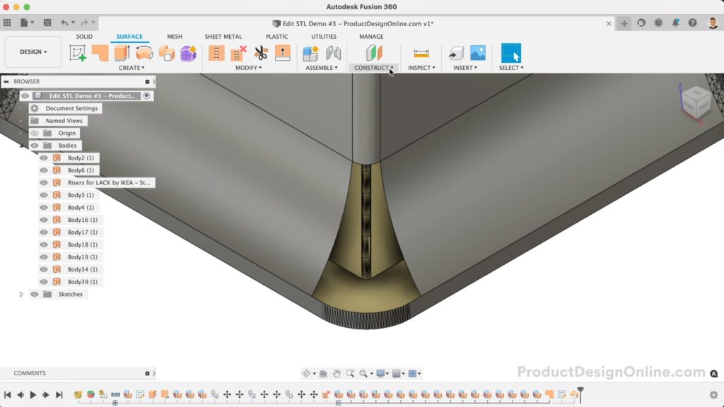
Demo Files
Use the following three demo files to follow along with the tutorial. During the tutorial video, I will call out when to use the next demo file to save you time from having to complete the laborious steps. Of course, you’re also welcome to complete all the steps on your own using the first demo file.
The demo files are all available for free via the PDO portfolio on Thangs.com. Important: You will need to convert each demo file with the Convert Mesh command in Fusion 360, using the ‘Faceted’ approach. This process is covered at the beginning of the Import and Edit STL tutorial.
- Demo File #1 – IKEA LACK Risers Standard
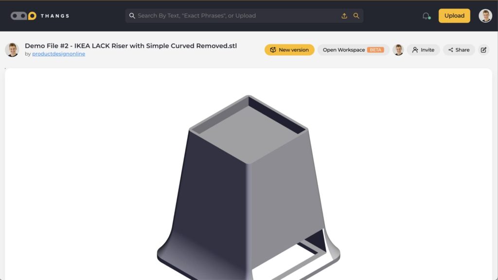
- Demo File #2 – IKEA LACK Riser with Simple Curved Removed
- Demo File #3 – IKEA LACK Riser with Complex Curves Removed
Video Tutorial – Import and Edit STL Files in Fusion 360 (2022)
Transcript
3D Printing hobbyists looking to remix STL files can clean up those pesky triangles using the following three techniques in Fusion 360. These range from beginner to more advanced difficulty. I’ll show you all three, including a way to version-control your STL files. The methods in this lesson are for those on the free Personal Use license without access to the newer Prismatic conversion.
To import your mesh file, always use the Insert Mesh command from the Insert dropdown menu instead of uploading your mesh file to the Data Panel. The insert workflow is best as it allows you to select the desired unit type. We can also use the rotation manipulators to reorient the model, followed by re-centering it to the origin point of our file.
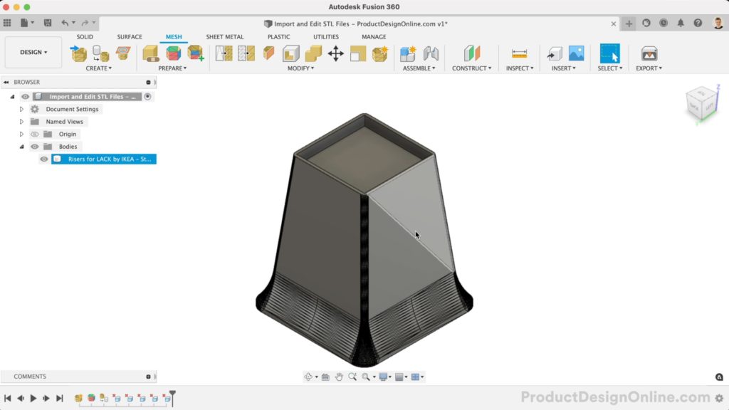
While in the Design workspace, we’ll head to the Mesh tab.
I’ll convert this table riser for an IKEA LACK table. Get the file link in the video description.
First, we’ll want to Generate Face Groups. This feature will detect groups of faces representing a feature or region of the mesh body. Using the Accurate option will provide the best results.
If you don’t see the pastel colors, you’ll want to turn on Face Groups in the Mesh Display settings. Notice how this has color-coded the model to show all the faces that relate to one another.
You will find a Convert Mesh command in the Modify menu of the Mesh tab. Double-check that you’re in the Mesh tab if you don’t see the Convert Mesh feature. You can also press the keyboard shortcut letter “S,” as in Sierra, to search for Convert Mesh.
After selecting the mesh body, you’ll want to choose whether you want the feature to be parametric and recorded in the timeline below. Or, for it to be a base feature if you plan to work with a direct editing approach. Generally, you’ll want this to be parametric, allowing you to update or remove features later.
If you’re on the free Personal Use or “Hobby” license, you’ll have no option but to use the Faceted approach. Those on all other license types can use the Prismatic version, which you’ll find will automatically convert most models to a clean and solid bRrep body, as if we created it natively in Fusion 360.
Back in the Convert Mesh feature, note that there is also a new Organic option. This method converts organically shaped meshes to solid, surface, or T-spline bodies. However, it is only available through the new Product Design extension.
Let’s proceed with the free Faceted method, and we’ll look at how to clean up the mesh triangles.
For starters, double-check the bodies folder in the Fusion 360 Browser. Your file should be a solid body, as indicated by the gray cylinder. If you ended up with an orange surface body, you’ll have to find and close the openings.
The first and easiest method to clean up these triangles is to select a planar face and press the Delete key.
Fusion 360 will attempt to self-repair all adjacent planar faces, resulting in a single face. This will provide you with a clean planar face to create a new sketch on. You can also Extrude or Offset faces to alter the dimensions.
One important note – you may find that offset faces will limit the size due to curvature or adjacent faces. You can avoid this by turning off the parametric timeline to enter Direct Modeling mode. You’ll find Direct editing to be more forgiving, but keep in mind that you do lose the parametric timeline and your ability to update any previous and future actions.
This delete faces approach does not work on any curved surfaces, as reducing the number of faces will modify the curvature itself. Instead, we’ll take a look at workflow number two, which is to use the orange Surface Extrude to rebuild simple curvature, such as this singular curved surface.
We can use the selection filters to turn off everything except Body Faces. Double-check the select through option is turned off to ensure we don’t select faces on the opposite side of our model.
We can then use the Paint Selection type by clicking on the Canvas – outside the model – and dragging over the desired faces.
Hold CMD on Mac or CTRL on Windows and click with your mouse to deselect any unwanted faces. Then, extremely critical, you must switch to the Surface modeling tab before pressing the Delete key.
Deleting while in the Surface tab will remove all of these outer faces, resulting in a surface body. We’ll now recreate this curve with a single surface.
To close the gap, you may be able to reference existing geometry with a surface Extrude. However, in this case, it leaves us with many faces. We can instead create a new sketch with projected reference points, allowing us to create a clean surface.
I’ll create a new sketch from the YZ origin plane. Creating this in the middle allows us to leverage the symmetric extrude type.
With Project, I’ll project the top and bottom points. Then, most importantly, we can recreate this exact geometry with a 3-point arc, so we’ll Project a point in the middle as well. If you’re not familiar with the Project and Intersect commands, be sure to watch my full lesson on them. Utilizing Project will be critical in rebuilding the surfaces of your mesh files.
With a 3-point arc, we can quickly recreate that exact surface.
Using the surface Extrude set as symmetric, we can extrude up to the edge by selecting the corner point. As you rebuild your files, consider how you may rebuild surfaces with the simplest geometry. You will need to break the object into multiple sections.
Note this surface is inside out, as noted by the yellow color. Use Reverse Normal to flip the surface.
Many models will include symmetry or the same geometry throughout. In this case, we can delete the faces of the other three curves.
If you’d like to follow along, you can use Demo File number 2. This file is set up with the other three surfaces removed.
The rebuilt surface still exists on its own in the Browser. This allows us to copy and paste using the standard shortcuts.
Then, you’ll find it very easy to place these into position by rotating them 90 degrees, followed by the Point to Point Move Type. Point to Point allows you to select the point you want to move as the “Origin,” along with the target point. Which corners you choose does not matter, as long as they correspond to one another. Simply repeat this process for the remaining two surfaces.
Now on to the third and most advanced method. If the model was originally built in Fusion 360 or an equivalent parametric program, then nearly all of the geometry can be rebuilt with a surface Sweep or surface Loft commands.
First, ask yourself if it’s easier to rebuild the model from scratch. In many cases, it may be worth the bit of extra time to have a truly parametric model.
If not, consider how you can divide the model up into sections that can be rebuilt with sweeps and lofts.
Fillets with single curvature can be rebuilt with the Sweep command. For example, we’ll rebuild the side of this table riser.
Here’s a handy trick if you need to delete a large number of mesh facets. We can use the Unstitch feature to unstitch the adjacent faces. Doing so will allow us to hide them in the Browser, making it easier for us to use a selection window to select all mesh triangles we’d like to delete.
For your convenience, you can also grab demo file number three, which has this section removed for you.
To create the sweep, we’ll need a sketch profile. In this case, we’ll sketch on the top surface to recreate the curvature.
Projecting the two adjacent lines will allow you to use the Tangent arc, ensuring there is tangency in the transition to the adjacent planar faces.
Using the surface Sweep command, we can now use this sketch as the profile, and the existing edge of our planar face as the Sweep path.
The next objective is to use a more complex surface Loft to fix the complex curvature at the bottom.
Lofting will generally require you to create one or more sketches to reference as the guide rails. In this case, we can loft from one side to the other, while referencing the top and the bottom as rails. However, because the bottom surface was not yet cleaned up, we’ll need to create a sketch to use as the rail.
With a Plane at Angle or Plane through Three Points, we can create a Construction Plane to create the sketch on.
Again, you’ll want to Project relevant geometry that will help you rebuild the surface. In this case, Project the corner edges and the start of the curve on each side.
We can draw lines for the two straight segments. Once again, I’ll use the Tangent Arc to ensure this geometry is tangent to the adjacent faces. Double-check that both tangent constraints applied correctly. You may have to manually apply them in some scenarios.
With the Surface loft, we can now use the top and bottom as the rails after selecting the two side profiles. Keep an eye on Chain Faces, which will ensure the sketch objects are selected as a single entity. You will also want to consider Continuity. We’ll switch this to Tangent (G1), which ensures the new surface is tangent to the adjacent surfaces.
You’ll also want to familiarize yourself with the various Analysis options that will help you confirm your geometry is correct and clean.
Once all your desired surfaces are rebuilt, we need to stitch them together to turn this model back to a solid body. Keep in mind that you do not have to recreate all surfaces, only the ones that you intend to modify and in some cases, any adjacent surfaces. As long as you do not reduce the number of mesh facets, the triangles do not actually affect the quality of the final model.
I recommend viewing your model with the Shaded visibility to check geometry throughout any of these workflows.
With the Stitch command active, you’ll find the red areas highlighted after we select the main body. Selecting each additional surface body in the Browser, you’ll find the highlights turn green, indicating that the surfaces are touching.
We’ll also want to set the tolerance. I recommend .01mm which will help close the surfaces without distorting them.
Notice we ended up with a single solid body in the Browser. You’re now able to modify this as a solid body, utilizing the full suite of solid modeling tools.
If you’re okay with losing your parametric timeline, you can use the Find Features command in the direct modeling mode. This may make it easier to remove or alter common features such as Extrude and Fillet.
I also want to show you how to use Thangs’ new Workspace to version control your files outside of Fusion 360. There’s always room for improvement after testing 3D prints, and I believe this workflow may help you keep track of changes and manage your files without crazy naming conventions.
From your Thangs.com Profile, select View My Thangs. You can then select the desired file and “Open Workspace.”
Thangs Workspace is 100% free and includes unlimited storage, sharing, and collaboration features.
Drag and drop the latest file and select Continue.
One of my favorite features is the ability to add a version description. Let your teammates or others recognize the improvements or changes. We can then Publish the new version.
It’s important to note that Workspace works with all of your private files, as well as your Public files. Your files do not have to be public to utilize these features.
From the Overview tab, compare differences side by side. However, in some cases, the changes may be hard to spot. The Overlay option allows you to drag the slider to transition from the latest to the new version. Notice the model turns solid green as it shows the new version.
Lastly, the X-ray feature allows you to quickly view any internal changes. This also calls out features that may have been removed or added, and you can toggle these options at any time.
All of these features can be activated from the desired version in your version history. Simply select to view the difference.
It’s also important to note if your model is already made public, then your new version will be made public immediately, so don’t upload the version until you’re ready…or you can always first change the model to be private.
Thangs’ new Workspace features also work hand-in-hand with their existing storage and collaboration features. Invite teammates to private folders and assign tasks based on each version or part. This makes working on collaborative projects much easier.
If you’ve learned something in this video, then you can help me out by clicking that thumbs-up button and sharing this video with your fellow 3D printing hobbyists.
You’ll also find additional 3D printing design lessons in the following playlist.
Hi Kevin,
first of all I´d like to thank you for your tutorials. Great help!
Unfortunately I´m stuck at one point in Workflow #3: Surface Model Complex Curves (Advanced).
I followed the procedure you are showing exactly (I think), but when I get to the point to close the gap (your video time stamp 10:13) by setting a tick at Chain Selection and then choosing the lower corner we sketched just before, that curve seems to be interrupted (the left straight part does not light up in blue, only the curve and the right straight part) and the gap can´t be closed by Fusion. Everything is tangent.
Could you please give me a hint, what the issue might be? 🙂
Thank you in advance and have a great Sunday.
Hello from Switzerland.
Oliver
Hi Oliver,
Glad to hear you’re enjoying the tutorials! This specific request is hard to help with without seeing your file, as it could be a number of things. Could you kindly share some screenshots and the Fusion 360 file in the PDO Community?
You can post it here: https://community.productdesignonline.com/c/fusion-360-questions/
Cheers,
Kevin
Would it be possible to have you perform a prismatic mesh conversion on an stl for me? I need to be able to edit this stl as if it were created in fusion. I want to add filets and much more. Just can’t do it with 9 million triangles, haha. TIA
Hi Jim,
Kindly share your file in my community space and I’ll give it a try: https://community.productdesignonline.com/
Cheers,
Kevin