Learn Autodesk Fusion in 30 Days (formerly called ‘Fusion 360’) is the most popular Fusion course online and was first launched in 2019. Since then, we have launched a revised 2023-24 version, and now we’re releasing a fully updated and improved 2026 version.
This is Day #1 of the 2026 Revised version of the course.
Full Course on YouTube
Watch the full course in this official PDO YouTube playlist.
Get the Day 1 Companion Guide (Step-by-step PDF)
Learn Autodesk Fusion faster with our comprehensive Day 1 guide. Serves as a standalone guide or the perfect companion to the Day 1 video lesson.
Making CAD education accessible to anyone, anywhere.
We hope you’ve been enjoying the wealth of free Fusion training provided by Product Design Online. Our commitment to empowering individuals like you with valuable skills is at the core of what we do.
If you’ve found our free content beneficial in your learning journey, we kindly ask for your support through a donation. Your contribution will not only help sustain the availability of free materials but also enable us to expand our offerings and reach even more learners globally.
Please select a donation method
Transcript
Your first challenge in Fusion starts right now: modeling this toy block. I’m Kevin Kennedy, and this is Day 1 of Learn Fusion in 30 Days. Today, we’re mastering the four tools used in 90% of 3D designs: 2D Sketch, Extrude, Shell, and Fillet. Let’s get started!
Each time you start a ‘New Design,’ Fusion prompts you to choose your design intent.
A Part Design represents a single manufacturable object, such as the toy block that you’ll create today.
An Assembly Design combines multiple parts to create a larger object. Think of it like building a structure with individual toy blocks.
Hybrid Design represents the ‘classic’ way of working in Fusion, where individual files can include both part designs and assemblies.
In the first few days of this course, we’ll start with a Part Design, as we create single objects. We’ll later dive into assemblies as you learn to create more complex objects.
You can also change the design intent directly from Fusion’s Browser by converting the Design Type.
For your convenience, I record all tutorials with Fusion’s default settings. Restore your settings to the defaults by clicking your profile and Preferences. Click the “Restore Defaults” button in the lower-left of the modal.
If the button is grayed out, then you’re all set!
The last thing we’ll want to do is set our default units. We’ll use millimeters for all 30 days.
On the left side of our Preferences, you will find Default Units for each workspaces. Select “Design” and make sure this is set to millimeters. Note that this sets the default unit for every new design file. However, you can change units of individual files at any time.
Be sure to select Apply to save the changes before closing the modal.
Locate individual design file units in Fusion’s Browser. Toggle open the Document Settings folder and click “Change Active Units.” Select your desired units. This change affects only this design file. However, notice we can also set the chosen units as the default. This will override the Preference that we previously looked at.
I’ll leave this set to millimeters and close the dialog.
Nearly all Fusion workflows start by creating a 2-dimensional sketch that you later transform into a 3-dimensional body.
We’ll start all new 2D sketches with the “Create Sketch” feature, located in the Toolbar or the Create menu.
Once activated, Fusion prompts you to select one of the three Origin Planes. These planes align with the X, Y, and Z axes.
Visualize the bottom plane as the floor or a table. The XZ plane faces you directly, while the YZ plane provides a side perspective.
To sketch the block’s length and width, select the bottom XY origin plane.
Watch closely as I select it.
Fusion automatically reorients your view to face the sketch directly. It’s an industry best practice to sketch in a straight-on view. This ensures precision by eliminating perspective distortion, making it easier to accurately place dimensions and constraints without accidentally snapping to background geometry.
You’ll also see that we now have a Sketch folder in the toolbar. Fusion displays contextual sketch tools only within an active sketch environment.
Select the 2-point rectangle tool to sketch the block’s basic shape.
Click the origin point to place the first corner of the rectangle. Starting at the origin anchors your design to a fixed point in space. This prevents your sketch from accidentally drifting and helps you ‘fully define’ the sketch with constraints and dimensions—a best practice we’ll discuss more later.
Notice two dimension inputs appear as I drag out my mouse cursor. Use these inputs to define the rectangle’s length and width.
Press the ‘Tab’ key to switch between inputs at any time.
To simplify things, I will supply the dimensions for every project in the 2026 edition of the 30-day course, allowing you to concentrate on mastering each tool and learning best practices.
I’m also offering detailed instructional guides that include common pitfalls, pro tips, practice challenges, and more.
Use the Tab key to ensure you’re on the width dimension. Type out 15.8mm for the width of the toy block.
Press the Tab key again to lock the dimension, then type 31.8mm for the length.
Click any of the four quadrants to place the rectangle. For this specific design, the direction does not matter.
If you need to make changes, double-click any dimension to reopen the input… and press Enter to save a new value.
You might notice your sketch lines changed from blue to black. In Fusion, black means the geometry is ‘fully constrained,’ while blue means it could still be moved. We’ll master this ‘Fully Defined’ state in the coming days.
Once your sketch is ready, look for the ‘Finish Sketch’ button in the top right. This is your ‘exit door’ back to the 3D world—Fusion needs to know you’re done sketching before you can use 3D tools.
We now have a “Sketches” folder in the Browser. Think of the Browser as the ‘table of contents’. It will list bodies, sketches, construction geometry, and more – including the sketch you just created. You can toggle the visibility of items by clicking the eyeball icon.
It’s time to transform this 2D sketch into a 3-dimensional model, using the Extrude command—the most common tool in the Design workspace.
Activate Extrude from the Solid toolbar, the Create menu, or by the keyboard shortcut letter “E” for Extrude.
Because we only have a single object in our sketch, Fusion will automatically select our “Sketch Profile.”
Type 9.6mm to define the thickness. This value populates the distance field in the Extrude dialog. Features allow you to define values in the Canvas or the dialog.
The current orthographic view hides the block’s depth. Click the ‘Home’ icon (next to the ViewCube) to switch to a 3D perspective. While you design, you’ll often switch from orthographic to perspective views.
Before we continue, let’s practice some navigation. Getting comfortable moving around your object is key to working efficiently.
Zoom in and out by using the scroll wheel on your mouse. Hold down your scroll wheel and move the mouse to ‘pan’ around. Hold the Shift key and the scroll wheel together to ‘orbit’ or rotate. This is an alternative to rotating with the ViewCube.
The home button is also a great way to reset your view at any time.
Let’s click OK to confirm the Extrude. A ‘Bodies’ folder now appears in the Browser. Like sketches, Fusion lists all 3D bodies here, allowing you to toggle their visibility.
As you design in Fusion, the Parametric Timeline at the bottom of the screen records every action. Think of this as ‘time travel’ for your design. It enables you to double-click and edit features—like changing your Extrude thickness—at any time. The rest of your model will automatically update to match.
Right-click on timeline items to perform other actions, such as Delete.
Now that we have the basic shape, don’t go anywhere. The Shell tool we’re about to use is like a ‘cheat code’ – it hollows out the block in a single click.
Before you continue, select the Save icon in the Application bar. Autodesk Fusion has cloud-based file storage, which means your files are stored on Autodesk servers instead of your local computer. This enables you to access your files from any computer.
Define the file name as ‘2×4 Toy Block’, and let’s set up a Project for the location.
In Fusion, your work is organized through a simple hierarchy: Projects are the top-level containers. Folders provide additional organization inside Projects, allowing you to group individual design files.
Click the caret icon next to the Location field to expand your Projects and Folders.
Click New Project and type “Learn Fusion in 30 Days” to create a new Project or top-level organization. Save all designs in this course within this Project.
Let’s also create a Folder to organize the first 15 days. First, double-click the Project to ensure it is selected. Click New Folder and type ‘First 15 Days’ for the folder name.
Many people find this confusing: you must double-click the folder to open it, ensuring the file is saved inside the folder.
Click “Save”.
The design tab now displays the file name and version number.
Effective use of versioning will be covered later in this course.
You can access your saved files in the Data Panel, at the upper left of Fusion. You can also create new Projects and Folders here, as well as move files around.
Let’s go ahead and finish off the toy block by designing the “studs” on top.
We’ll start by sketching a 2D circle on the top. Select ‘Create Sketch’ to begin. Now that we have an existing 3D body, select the top planar face of the block to sketch directly onto the 3D body.
Select the Center Diameter Circle or use the keyboard shortcut letter “C” for Circle.
Click once to place the center—and don’t worry about the position yet. Type 5mm for the diameter and click again to place the circle.
Fusion keeps the sketch command active until you press Escape or activate another command.
Remember, if you make a mistake, you can double-click any dimension to make changes.
If I click and drag the circle, it can still move around freely. In Fusion, you apply constraints and sketch dimensions to lock your objects in place.
Select the Sketch Dimension tool in the toolbar or activate it with the shortcut “D” for Dimension.
Select the circle’s center, then the top edge of the rectangle. Drag your mouse to the left. A dimension will appear, allowing you to define the distance between our two selections.
You must click again to place the dimension.
Type 3.9 and press enter. Note that we do not have to type “mm” for millimeters, as we set that as our default unit of measure.
Let’s repeat the previous steps in the other direction, also entering 3.9mm for the distance.
Take a moment to try select and drag the circle. Notice it will not move as these two dimensions keep it in place.
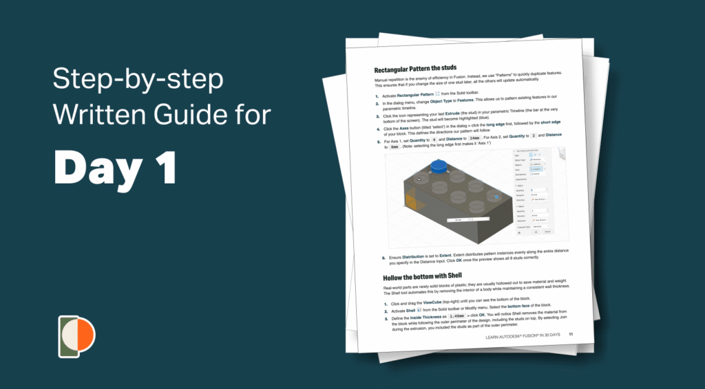
At this point, we could manually draw all of the other circles, but it would be much more efficient to use the Rectangular Pattern feature.
Here’s an important best practice. Fusion offers both Sketch and Solid Modeling versions of the Rectangular Pattern tool.
Avoid the temptation to use the Sketch Rectangular Pattern. Fusion performs significantly better when you pattern 3D bodies or features instead of sketch geometry because it’s less taxing for Fusion to process. Keeping your sketches as simple as possible ensures a fast, responsive model that is much easier to update later.
Press “E” on the keyboard to activate Extrude.
Select the circle profile. Since the sketch contains multiple profiles, Fusion requires you to specify which one to extrude.
Define the distance as 1.7mm. Before clicking OK, notice that the Operation defaulted to “Join.” Keep this setting, as it fuses the new cylinder to the existing block, resulting in a single 3D body. In contrast, the “New Body” option would create a separate, disconnected 3D body.
I’ll show you why this “Join” is critical in just a minute when we hollow out the bottom of our block.
Click OK, then activate Rectangular Pattern from the Solid toolbar.
The pattern “Type” allows us to toggle between Circular, Rectangular, or Pattern on Path.
The most important is the “Object Type”. Set the ‘Object Type’ to ‘Features.’
This allows you to select the Extrude directly from the timeline as the object to pattern.
Notice the cylinder turns blue when our Extrude is selected.
Define the pattern direction by clicking the Axes selector, then select the block’s length edge and the width edge. This is because our toy block studs are in two rows of four, so we’re patterning this single instance in both directions.
Make sure to select the length first so it correlates to our Axis 1 in the dialog. This will ensure your dimensions match mine.
Notice we have two directional arrows on the model. Drag the directional arrows to start the pattern. This visual check ensures you are heading in the right direction before entering exact numbers.
You’ll define the length first by modifying Axis 1. Set the distance to 24mm and the quantity to 4.
One important note: Make sure the Distribution defaulted to ‘Extent.’
Extent defines the total distance from the first stud to the last, rather than the space between each individual stud.
Axis 2 will get a quantity of two, representing the second row of studs, with an Extent distance of 8mm.
At times, to keep the pattern in the right direction, you may need to add or remove the minus symbol from the distance field.
Click OK to save the pattern if the preview looks correct.
If yours is off, double-check that the “Distribution” is set to “Extent” and make sure you selected the correct edges of the block. We’ll continue to discuss the Distribution types in future days of this course.
We’re just about done with our toy block. We can look at the bottom of our block by clicking and dragging our ViewCube. The ViewCube allows you to quickly switch between standard orthographic and isometric views.
Our block is still solid, but we’d like to hollow out the bottom to mimic a real one. In Fusion, we can use the Shell command to hollow out the solid 3D body.
Find ‘Shell’ in the Modify menu, as you are modifying an existing 3D body.
We can select faces or bodies, which determine how the object is hollowed out. Select only the bottom face. This ensures the Shell tool leaves the four outside walls.
Set the ‘Inside Thickness’ to 1.49mm. The Shell tool traces the body’s outer contour, leaving the defined thickness. Because you ‘Joined’ the studs earlier, the Shell command includes them as part of the outer contour, leaving these indents inside the studs.
Click OK to confirm the Shell.
Lastly, we’ll draw the three center columns at the bottom of the block.
New sketches can also be created by right-clicking on an existing planar face. Right-click the bottom inside face and select ‘Create Sketch.’
Make sure that you’re selecting the correct inside face and that your sketches in the Browser are turned off so they’re not in the way. Fusion will automatically hide sketches after you select them with a modeling feature.
Let’s activate the Line command from the toolbar.
We’ll start by enabling “Construction” in the Sketch Palette. This line is for reference purposes only. Construction lines – which become dashed lines – help you align your geometry, but won’t interfere with the sketch profiles, as you select them for 3D modeling features.
Then, because we’re looking at an orthographic straight-on view, you’ll find we can reference some of the existing geometry. Referencing our model’s geometry will not work if you view it from a perspective.
You can always click “Look at” in the Sketch Palette to look directly at the sketch.
To create this line, I’ll move my mouse cursor over a recessed circle. A circle glyph will appear, allowing you to snap the cursor to the center of the circle.
Draw the line across and click the center point of the opposite circle.
Press Escape to clear the Line command.
With the Center Diameter Circle, we now have a reference line to find the exact midpoint, or middle of the line.
Be sure to disable the Construction option in the Sketch Palette or press the shortcut letter ‘X’.
Find the midpoint where the triangle glyph appears. Click to place our circle and define the diameter as 6.3mm.
As an alternative to the Shell command, sometimes we may want to extrude a profile with two defined sketch objects.
We can use the Offset Sketch tool. Select the circle and type out 1mm for the offset distance. Use the Flip button until the circle is on the inside.
Offset helps you quickly create the same geometry a specified “offset” distance from the original.
You can now extrude this cylinder into a 3D body. Define the distance as 8.1mm and click OK.
Once again, let’s use the Rectangular Pattern feature. Because you used it recently, it defaults to the ‘Features’ Object Type. Select your latest Extrude from the timeline.
Click the Axes selector, then select the block’s long edge.
Enter 3 for the quantity and 16mm for the distance, then click OK.
If you now rotate the toy block around, you’ll see that we have completed the overall shape.
The very last thing you’ll want to do is add a Fillet to round off those sharp edges. Pro tip: In CAD, we pronounce it ‘fil-it,’ not ‘fill-et’ like the fish!
Activate Fillet from the Modify menu or use the shortcut letter “F” for Fillet.
Take a minute to select all eight stud edges. Then select the outer edges of the block, followed by the base edges of the three bottom cylinders. When selecting, be careful to click the edge, not the flat surface of the face. Fusion is sensitive to exactly what your cursor highlights, and selecting a face would fillet every edge attached to it, which often includes unwanted edges.
Define the fillet radius as 0.2mm.
Don’t forget to save your design once you’re finished.
Great job completing your toy block! Click here for Day 2, as we look at using reference images to create a glass soda bottle.