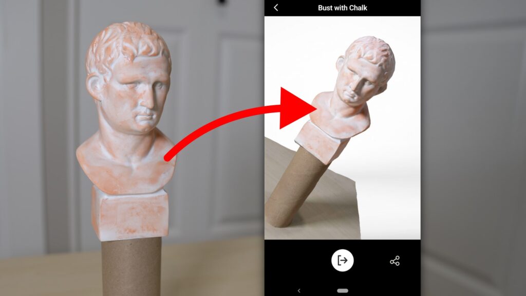
What is Photogrammetry?
Photogrammetry can vary, but the process revolves around gathering measurements and information from a collection of photographs.
Like the human eyes, photogrammetry obtains depth and perspective by using photographs from at least two vantage points. Typically, you’ll need to capture fifty to several hundred photos to produce highly detailed results. The accompanying software will then process and stitch together the photographs, resulting in a 3D model.
You can practice photogrammetry with high-end DSLR cameras, smartphones, and even drones! Ultimately, the number of photographs you need to capture will depend heavily on the object.
Prussian architect Albrecht Meydenbauer coined the term photogrammetry, which appeared in his 1867 article “Die Photometrographie.” Despite its long existence, photogrammetry is gaining significant traction thanks to advances in technology and software.
Smartphones paired with cloud computing now make it easier than ever to 3D scan any sized object using photogrammetry.
How to 3D scan with your Smartphone
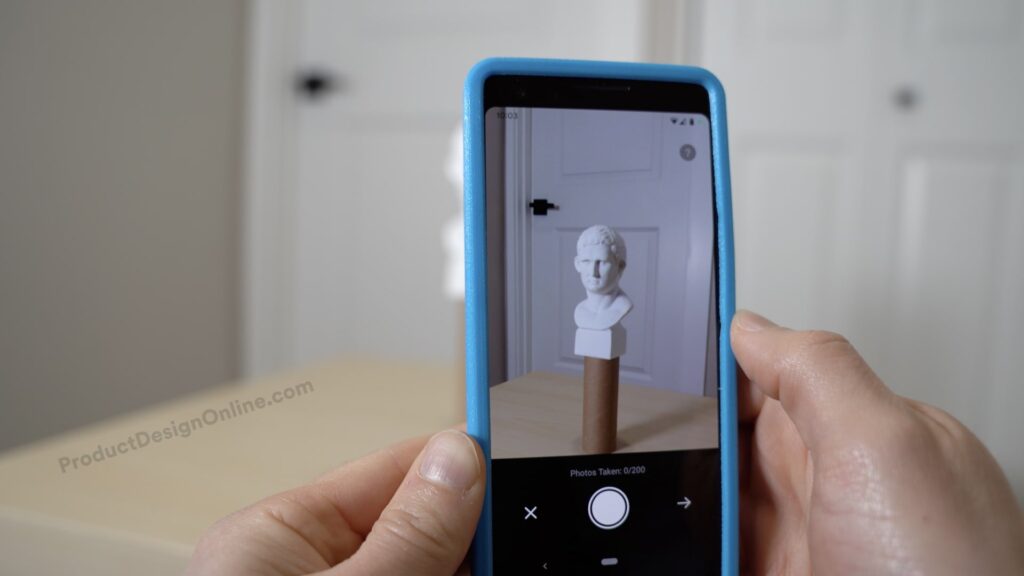
3D scanning with a smartphone comes in two forms – Lidar and Photogrammetry.
Photogrammetry is most accessible as it simply requires any phone that can capture images. The accompanying software can leverage complex measuring algorithms to stitch the photographs together, outputting a 3D model.
Lidar, which stands for Light Detection and Ranging, requires specific hardware. Recent iPhone and iPad models (2021 and newer) include Lidar capabilities. Thought, Lidar is not something possible with all smartphones or tablets.
Lidar uses a pulsed laser to measure variable distances by targeting an object or surface. The laser measures the time for the light to return to the receiver.
Lidar is also the same technology being used with many self-driving car applications.
For 3D printing hobbyists, we recommend using Photogrammetry as it often produces better results without requiring new hardware.
Using the KIRI Engine App to 3D Scan

We recommend using the KIRI Engine app for 3D scanning with your smartphone. KIRI Engine is available for both iPhone and Android phones. Note: The Android app was re-launch in March 2023.
KIRI Engine uses cloud computing to process your 3D scan. Cloud computing will provide better results while also allowing you to continue to 3D scan additional objects. This is also the only smartphone photogrammetry app that we’ve found to consistently produce better results than Lidar 3D scanning with an iPad Pro.
Follow our best practices outlined below to get highly detailed and accurate 3D scans with your smartphone.
We also have a tutorial video covering 3D scanning with your smartphone using the KIRI Engine app. At the end of the tutorial, we share some tips for cleaning up your 3D scan data with Autodesk Fusion 360.
5 Tips for Successful Photogrammetry with Smartphones
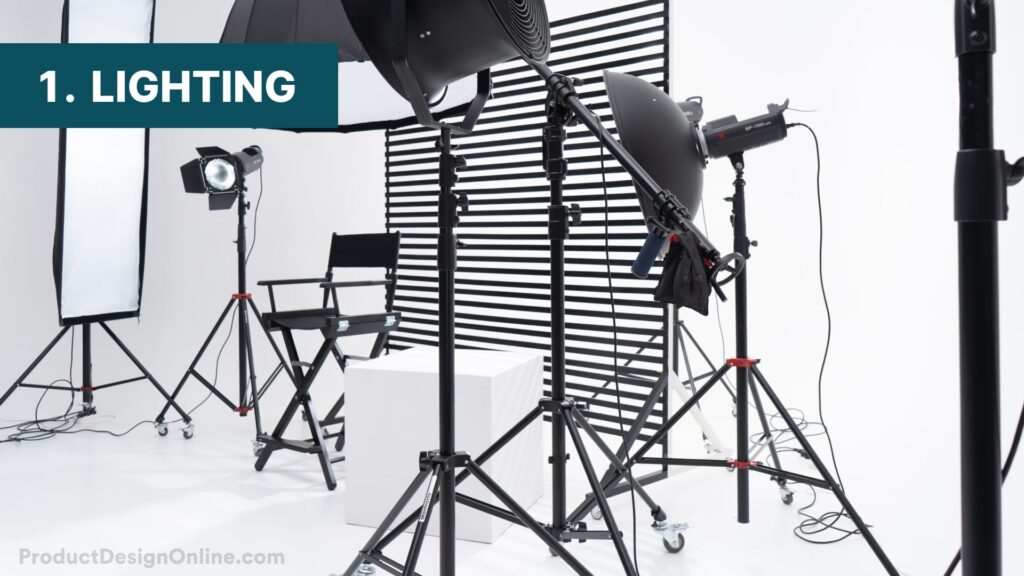
1. Lighting
The most critical consideration in prepping for photogrammetry is your lighting. Avoid hard shadows at all costs. Some shadows cast on the model are okay.
For best 3D scan results with photogrammetry, I recommend finding a place away from any windows. Sunlight will change while you snap the photos, so you need a controlled environment. Use a windowless room or hallway.
Using a softbox or other photography LED Panels will help you light the object evenly without hard shadows.
If you are on a strict budget, find a recessed light in your hallway, then locate the object directly under it. Overhead lighting will help minimize hard shadows from being cast in a single direction. Depending on the size of your object and the lumens of your light, this may or may not work.
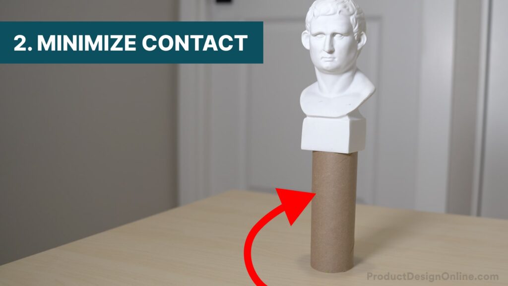
2. Minimize Contact Area
A 3D scan result is only as good as the usable mesh data. Many run into issues with the table or surface area touching the desired part.
Minimizing the contact area with the desired 3D object and the table or surface area will make cleaning up the scan data easier.
Before you start to 3D scan, find something to prop your object above your surface, such as a toilet paper roll. Toilet paper rolls will make cleaning up the final scan much easier, as the table or ground surface will have less contact with the bottom of the model.
Propping the model also helps reduce unwarranted hard shadows.
Lastly, this technique helps when working with round objects or organic surfaces that don’t have a planar bottom.
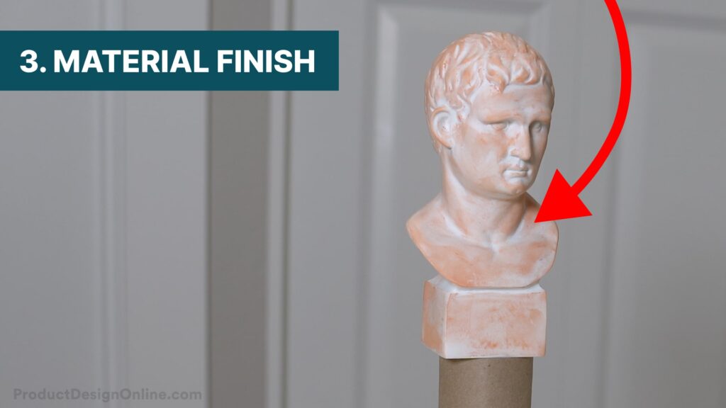
3. Material Finish
Consider the material or surface of the object itself before you start to 3D scan. Anything with metallic or reflective surfaces will need to be spray painted or covered by another material.
If you have issues with solid white or other light or solid surfaces, you can take a piece of sidewalk chalk and rub it over the object. The additional color will give the photos more detail to reference, resulting in a highly detailed scan.
Adjust your lighting based on the object. You may need to turn down the brightness of the LED panels or reflect light off the ceiling to better light the desired 3D scan.
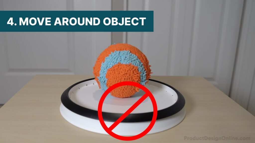
5. Move Around Object
Using a turntable is generally not recommended with smartphone-based photogrammetry, as the elements in your background are what help the app stitch photos together at the correct scale. You should also avoid using a solid backdrop.
Moving around the desired object will provide the accompanying software with more data to reference.
It’s critical that the object doesn’t move at all when taking photos. Always set up your 3D scan in an area where there is sufficient room to walk around it. Make sure the table or surface will not vibrate or get bumped.
As you start to take photos, make sure to have a significant overlap versus no overlap. Otherwise, your final 3D scan will have large holes that you cannot fix.

5. Photos in Layers
Try to take the photos close to the model to capture more details, but keep in mind that some background items should always remain in each photograph.
Most importantly, be sure to take photos in different layers. After going all the way around the object, do the same thing at a higher and lower level. Generally, I recommend going 360 degrees around the object once before changing height, as it’s easier to make sure you get every angle.
For the best 3D scan results, take 50-200 photos, depending on the object and the amount of detail you’re trying to capture.
Tutorial Video – 3D scanning with a smartphone
Transcript
Photogrammetry, or “3D scanning” with smartphone apps, often produce undesirable results, but the five following techniques will help you get detailed and accurate 3D scans with any iPhone or Android phone.
The most important consideration is your lighting. Avoid hard shadows at all costs. I recommend finding a place away from any windows, as sunlight will change while you snap the photos.
For best results, use a windowless room or hallway. Use some LEDs to light up the entire object. A softbox or other photography lights will be helpful. The cheaper alternative is to find a recessed light in your hallway, then locate the object directly under it. Overhead lighting will help minimize hard shadows from being cast in a single direction.
Before you start to 3D scan, find something to prop your object above your table’s surface, such as a toilet paper roll. This TP roll will make cleaning up the final scan much easier, as the surface will have less contact with the bottom of the model. Propping the model also helps reduce unwarranted shadows.
Consider the surface of the object itself before you start to 3D scan. Anything with metallic or reflective surfaces will need to be spray painted or covered by another material. If you have issues with solid white or other light or solid surfaces, you can take a piece of sidewalk chalk and rub it over the object. The additional color will give the photos more detail to reference, resulting in a highly detailed scan.
I recommend using the new KIRI Engine app, as they offer free 3D scanning on both iPhone and Android.
Unlike most smartphone 3D scanning apps, KIRI Engine processes each 3D scan using cloud computing. Cloud computing gives you more details and better results than what your phone could process and also means you can start additional 3D scans while they’re processing.
This is the only smartphone photogrammetry app that has consistently produced better results than Lidar 3D scanning with my iPad.
To start scanning, select the plus symbol and take photos. It’s critical to keep the object sitting perfectly still. Snap the first photo, then move 20 to 30 degrees over and snap another. It’s always best to have a significant overlap with your photos versus no overlap. Otherwise, your final 3D scan will have large holes that you can’t repair.
Using a turntable is generally not recommended with smartphone-based photogrammetry, as the elements in your background are what help the app stitch photos together at the correct scale. You should also avoid using a solid backdrop.
Try to take the photos close to the model to capture more details, but keep in mind that some background items should always remain in each photo.
Most importantly, be sure to take photos in different layers. After going all the way around the object, do the same thing at a higher and lower level.
For the best 3D scan results, you’ll want to take 50-200 photos depending on the object and the amount of detail you’re trying to capture.
Once you’ve finished taking photos, type out the model name and choose your file format and model quality.
Select “Upload,” and the photos will be sent to “the cloud” to process. Back on the home page, you’ll see the project status. It should take about 5-20 minutes to process, though this will vary based on the number of photos you use.
Once complete, you’ll be able to preview your 3D model right on your mobile phone. Viewing results in minutes makes it easy to double-check the results are sufficient before sending them to your computer.
To 3D print or modify your scan with a CAD package, select export, copy the link, and paste the URL into your web browser.
Select “Download Model,” which will download an OBJ file of your model. The zip folder also includes a few additional file types.
OBJ files store 3D information as a list of vertices joined by edges. Unlike STLs, they support polygonal faces that allow for a closer representation of the original geometry. They also include a texture map, which wraps a crazy-looking 2D image around your 3D model to include the visual information.
To clean up or modify your 3D scan in Fusion 360, always head to the Insert menu and use the Insert Mesh option. The Open or import workflows will not allow you to adjust the orientation.
Note the KIRI Engine app includes both a high-quality and low poly OBJ file. You’ll see the amount of detail is quite different.
I’ll flip this up 90 degrees. I also like to turn on the Origin planes and reposition the model so the bottom of the TP roll is aligned with the bottom origin plane. Take your time to readjust the angle if needed.
Keep in mind the default Visual Style will show edge lines for each mesh polygon. Change the visual style to Shaded to see the 3D scan in full detail.
We can now use the Plane Cut tool to remove the entire table surface and unwanted mesh facets below. Select the mesh body and select the origin plane as the Cut Plane.
Drag the directional arrow up until the table surface is gone. We’ll discuss these details in a second. This cut is complete as I’d like to scale the file before modifying it further.
Like STL files, OBJ files are unitless. This means you’ll need to scale the file to the desired size.
Another reason I like to prop the scanned object on a TP roll or another common object is to help with the scaling. We can create a sketch on the origin plane and draw a line equal to 1.6 inches, or the diameter of the TP roll.
With the Scale Mesh command, select the mesh and define the bottom center as the point at which the scaling takes place.
Unfortunately, Fusion 360 does not currently have a way to scale to two defined points, so it’ll take a bit of back and forth to get this lined up with our reference line. This method only works for projects that don’t require precise tolerances. You can also check out Meshmixer and NetFabb for additional mesh functionality.
Once the object is scaled, open the Bodies folder in the Fusion 360 Browser.
Just about every 3D scan will include a warning that the mesh is not closed. This is because of the opening at the bottom of the object.
If you want to 3D print the scan, you’ll want to create a smooth planar face on the bottom surface, as well as fill the void. Fortunately, these can both be done with the Plane Cut feature from the Mesh menu.
With Plane Cut, we can select the mesh body again.
Select the bottom origin plane as the “Cut Plane.” Keep in mind that you can use any custom construction plane if you need a plane other than the default origin planes.
I’ll then drag the directional arrow to the bottom of the object. For more precise positioning, use the numerical inputs in the dialog.
The Plance Cut tool will default to “Trim,” which is what we want, as that will trim away everything up to the selected plane. Note that you can also split the body or faces, should you need to keep the mesh data.
Most importantly, you’ll want to change the Fill Type. Set this to Uniform or Minimal. Minimal will complete the action with the fewest amount of faces possible. Generally, using Uniform will provide the best results without disturbing the surrounding faces.
Depending on your 3D scan, this may take care of the warning in the Browser. If not, you can select the warning triangle in the Browser, which activates the Repair tool.
Use the “Close Holes” repair type to ensure you don’t have any unwanted openings in the model. This process will depend heavily on the object and the quality of your 3D scan. The time it takes to process and the results you get will differ.
You can also use the Separate tool to separate different mesh shells. This can be extremely helpful when you have scan data out in space that you’d like to remove. Once the bodies are separate, you can Remove the bodies in the Fusion 360 Browser.
You’re then all set and ready to 3D print the object, or use it to reverse engineer a part by referencing it directly in Fusion 360.
[upbeat music]
Special thanks to the new Patrons and those who supported the channel via my Buy Me a Coffee.
Here’s a video on importing and editing STL mesh files in Fusion 360.
[End upbeat music]
Thank you!
Thanks for stopping by, Trevor! Happy 3D scanning 🙂
Perfektný návod, inšpirovali ste ma! Už som 10 r. na dôchodku, učil som AutoCAD 2D, ale chcel by som ešte moje rezbárske práce publikovať v 3D.
Thanks for stopping by, Fulmek! Glad to here this was helpful.
I would like to make dolls from heads I have sculpted, building bodies from soft and hard materials to support the finished doll. How much should I expect such a head to weigh at about 2″ wide and 2.5″ from top of head to chin? Any ideas? Thanks
Here are some rough estimates based on different materials:
Polymer Clay: Polymer clay is relatively dense, and a 2″ wide by 2.5″ tall head could weigh around 50 to 100 grams, depending on the thickness of the sculpt and the specific type of polymer clay used.
Air-Dry Clay: Air-dry clay is generally lighter than polymer clay. For a head of similar size, you might expect a weight of 20 to 50 grams.
Resin: If you’re casting the head in resin, the weight can vary based on the thickness of the cast and the specific resin used. A resin head might weigh anywhere from 30 to 80 grams.
Remember that these are rough estimates, and actual weights can vary based on your specific sculpting techniques, the thickness of the material, and the density of the chosen medium.
I would like to make 3D scans of fossil footprints ( on nearly flat rock surface) using KIRI engine. Is it possible to get images in open sunlight?
Shadows can be a big challenge with 3D scans if there is too much light from one direction. You may need to use a photography light diffuser. It’s certainly possible though.