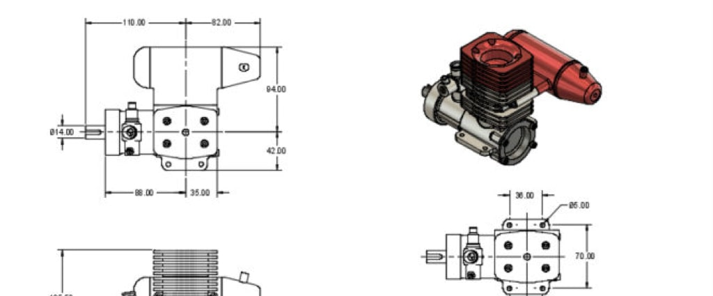
Whether you’re new to CAD or an experienced 3D modeler, you’ll want to familiarize yourself with best practices for dimensioning CAD files. Here are 20 of my favorite “best practices” to follow when dimensioning CAD drawings in Fusion 360. These are not in any particular order. Each rule should be treated with the same amount of consideration.
- Dimensions should NOT be duplicated. For example, if you dimension the right side of a part, the opposite (or left) side of the part should not be dimensioned unless it is different.
- No unnecessary dimensions should be used. Use the minimum amount of dimensions needed to produce or inspect the part. Unnecessary dimensions only make the drawing more cluttered and hard to understand.
- Never cross dimension lines. Crossed lines can make the drawing confusing which can lead to production mistakes. Always give dimension values plenty of spacing.
- Never cross extension lines. Similar to the dimension lines, any line(keyboard shortcut “L”) Creates lines and arcs. Select a start and endpoint to define a line segment. Click and drag the endpoint of a segment to define an arc. More extensions should be free from crossing paths with one another. Crossed extension lines make it hard to follow the line to the dimension value and can lead to production mistakes.
- Dimensions should be attached to the most appropriate view. Dimensions should be used on the view that best shows the shape of the feature to be dimensioned.
- Avoid dimensioning hidden lines. Adding dimensions that aren’t clearly visible causes a lot of confusion.
- Dimensions are placed about ½” away from the object, and never directly on top of lines or the object itself. Additionally, dimensions should be placed another ¼” to ½” away from other dimensions.
- Extension lines start approximately 1/16″ from the object and extendExtends a curve to the nearest intersecting curve or boundary geometry. Pause the cursor over the curve to preview the portion to be extended. Select the curve to extend it. More 1/8″ past the last dimension. Extension lines should never touch the object as it will not be clear where the object ends.
- Holes should be located in the view that shows the feature as a circle. This means that holes should never be dimensioned at a perspective.
- Holes should be located by their center lines.
- A circle is typically dimensioned by its diameter and an arc by its radius.
- All dimensions should be given in decimal format. When dimensions are given in inches, leading zeros are omitted from dimension values less than 1.00.
- When all dimensions on a drawing are given in inches, the inch marks (“) are omitted, the same applies to millimeters. If metric units are used, the word METRIC will appear in the title block.
- When there are several parallel dimension lines in a group, the dimension figures should be staggered so that they will not interfere with one another.
- Notes should always be placed horizontally on the page, to be read from the bottom of the drawing.
- Dimension lines for angles are drawn as arcs with their centers at the vertex of the angle dimensioned.
- Angular dimensions should be expressed in degrees and the figures should be placed horizontally.
- When dimensioning through crosshatching, the crosshatching should be broken around the dimension figures but not around the dimension line.
- When a dimension figure has been changed so that it no longer agrees with the actual scaled distance on the drawing, it is customary to underline it with a wavy line or mark it NTS (not to scaleScales sketch objects, bodies, or components. Select the objects to scale then specify the scale factor. More).
- Dimension numbers should be centered between arrowheads, except when using stacked dimensions then the numbers should be staggered.
Are there any dimension best practices that I missed in this list? Be sure to comment them below!

Leave a Reply