The most common command you’ll use in the T-spline or Form (Sculpt) environment is the edit form command. To get to the edit form command simply right-click on your selection of faces, edges, points, or a combination of all three. Then, select “edit form” from the marking-menu.
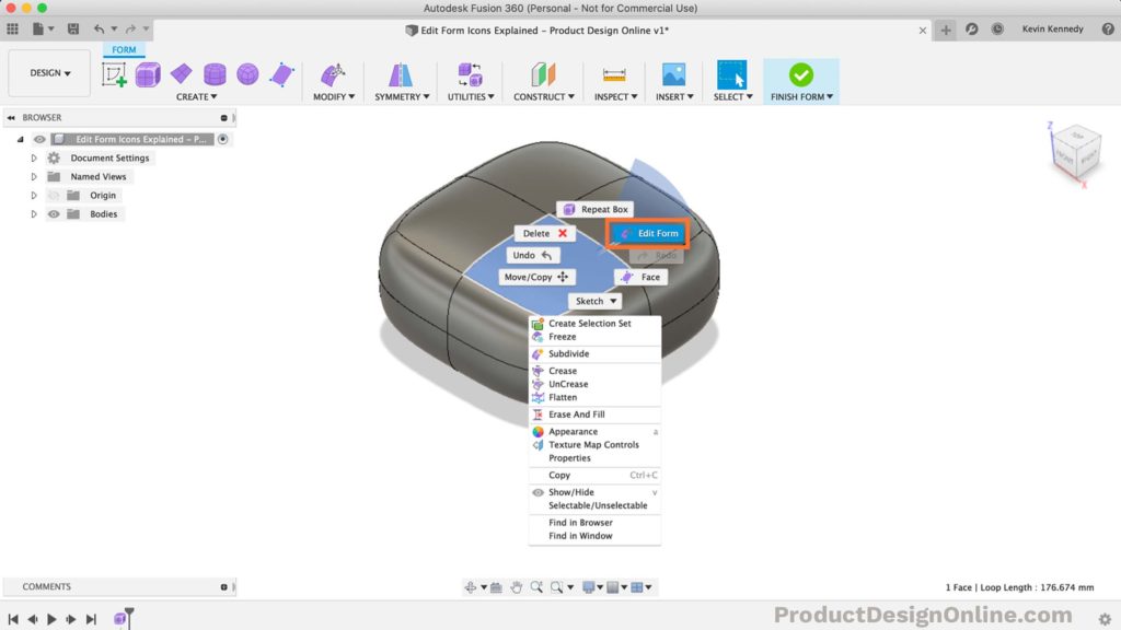
You can also access the edit form command from the modify dropdown list, or by using the keyboard shortcut letter “S,” which will bring up the search box. Then, you can simply search for the term: edit form.
After selecting the edit form feature you’ll be presented with the manipulator that hosts an assortment of tools. To master the Fusion 360 Form (Sculpt) environment, you’ll need to familiarize yourself which each icon.
In this article, I’ll explain what each icon represents and how to use them.
Single Axis Icon (Arrow)
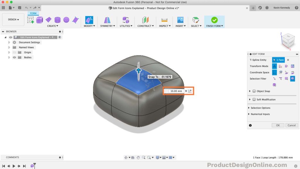
The arrow icon allows you to move your selected entities in a single axis direction. Essentially, the entities you have selected can be pushed or pulled along the X, Y, or Z-axis – whichever you select!
For example, in the image below I am clicking and dragging on the Z-axis arrow. If you try this yourself, you’ll see that you can pull it up or push it back down. You can also type in a specific distance in the dimension box, which is highlighted in orange.
One important thing to note is that when you move a face on a surface the surrounding faces move to maintain continuity. This means, the more you push or pull on a face, the more the surrounding faces are going to be pushed or pulled along with it!
Rotate Icon (Circular Arc Slider)
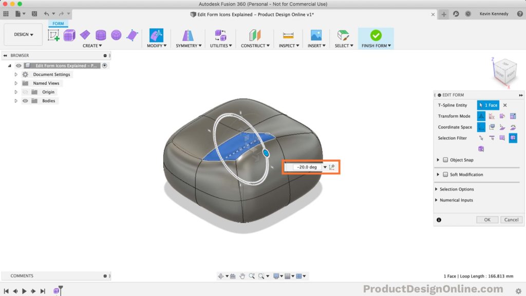
The rotate icon, or these circular arc sliders that are located just outside the single-axis arrows, allow you to rotate the selected geometry around a single axis.
Just like the single-axis arrows, the rotation sliders will follow the X, Y, or Z-axis. The rotation sliders will also work on a selected face, edge, point, or a combination of the three. You’ll also notice that as you drag the rotation slider around it will snap in place every 5 degrees and it will also snap into place at every 90 degrees. You can also type in your desired degrees in the dimension box, as highlighted in orange.
Finally, you need to be extremely careful when using the rotate feature, as self-intersecting faces, or geometry that twists through itself will cause errors and your model will not be able to convert back to a solid body.
Planar Direction Icon (Rounded Square)
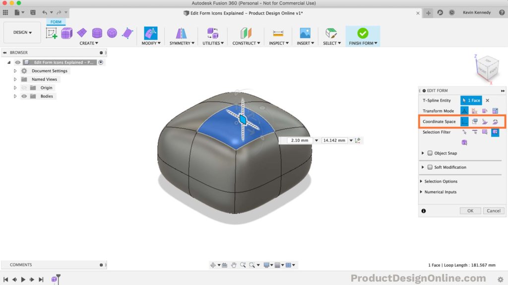
The rounded white square is the planar direction icon. Selecting and holding down the rounded square will allow you to move the selected geometry along the plane parallel to a given plane in the world space.
You can simply click and select the square and move it freely around the plane. By default, the edit form manipulator uses the world space coordinates or these X/Y/Z planes. You can also use the view space by selecting it under the “coordinate space” section of the edit form dialogue box (highlighted in orange).
The “view space” is based on the camera view. If you select view space in the edit form dialogue box, you’ll notice that no matter how you rotate the sculpted form the planar direction icon is always based on your perspective.
You can also select the local space icon, which will leave the planar direction icon based on the normal direction of the surface. If you view the object from another angle, the planar direction icon moves with it.
Single Direction Scaling Icon (Straight Line)
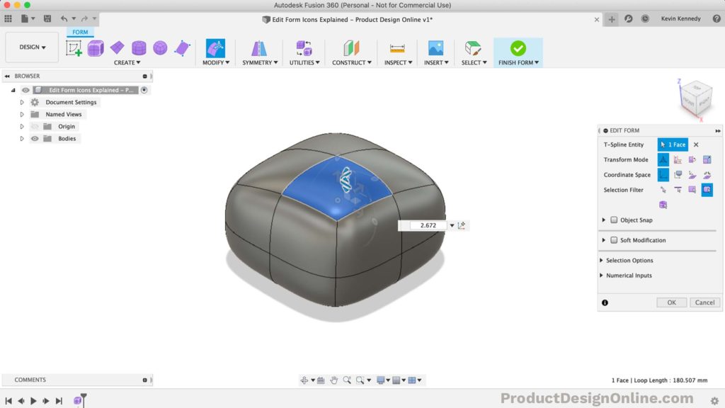
The single direction scaling icon, or the straight lines, allows you to scale the selected geometry in one direction.
Like the other icons, the single direction scaling icon also works on a selected face, edge, point, or a combination of the three.
To remember what this icon does, just remember that the straight line next to the single direction arrow is also a single direction action. The only difference is that the arrow moves the selected geometry, whereas the line scales the selected geometry.
If you select a face, select the straight line and drag your cursor upwards, you’ll see that it will increase the size of the face (or scale it to be much larger). Of course, if you move your cursor back down towards the middle of the model it will decrease the scale or size of the selected geometry.
Planar Direction Scaling Icon (Corner Line)
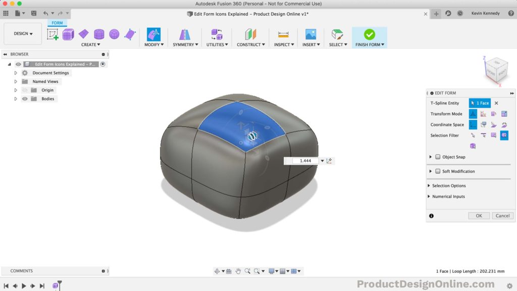
The second to last icon is the corner line, that allows you to scale in a planar direction.
To remember what this icon does, simply remember that the roundedness correlates to the rounded square, as both of these icons work in the planar directions.
Select any of the geometry, including edges, faces, points, or a combination of the three. Then, click and drag on the planar direction scaling icon, you’ll see it scales the size of the selected geometry along the plane.
Similar to the rounded square or the planar direction icon we can change the coordinate space to move along the desired plane other than the X, Y, or Z-axis.
One important thing to note is that the planar direction only works in two directions, as indicated by the little arrows (highlighted in orange).
Universal Scaling Icon (Center Circle)
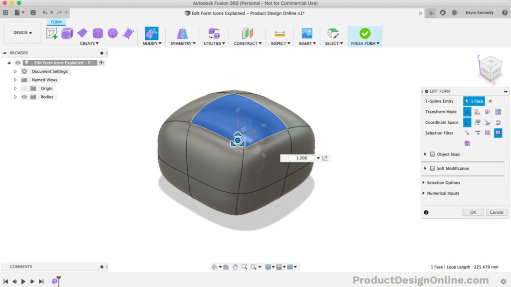
The last icon is the circle located directly in the center of all these manipulators.
This center circle is the universal scaling icon, which allows you to select any geometry and move the mouse left or right to scale the geometry in all directions.
Extrude a Face Command (Option/Alt Key)
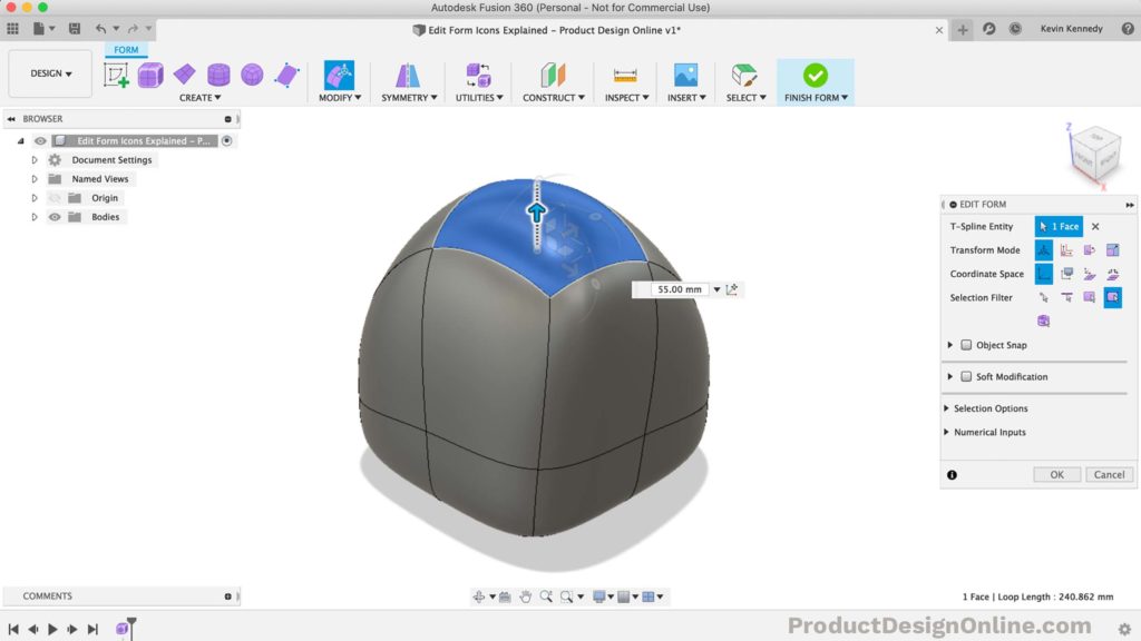
The last thing to note is that you can create new faces or add geometry while using any of these manipulator tools. To extrude new faces as you manipulate geometry simply hold down the option key on Mac or the alt key on Windows.
For example, if you select a face and hold down the option/alt key, you’ll notice as you pull the single direction arrow up it not only pulls the shape up, but it creates new faces on the sides. Holding down the option or alt key can make all the difference in the outcome of your model (as pictured below).
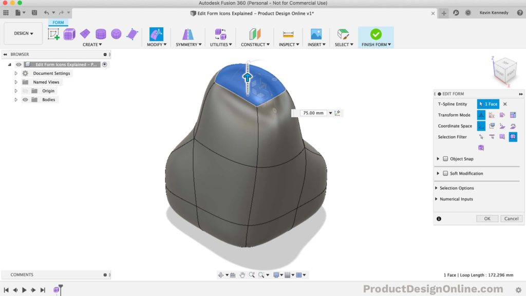
Note: If you try to use the option/alt key you may end up with an error message stating that the “Extrude operation can be applied only on manifold surfaces.”
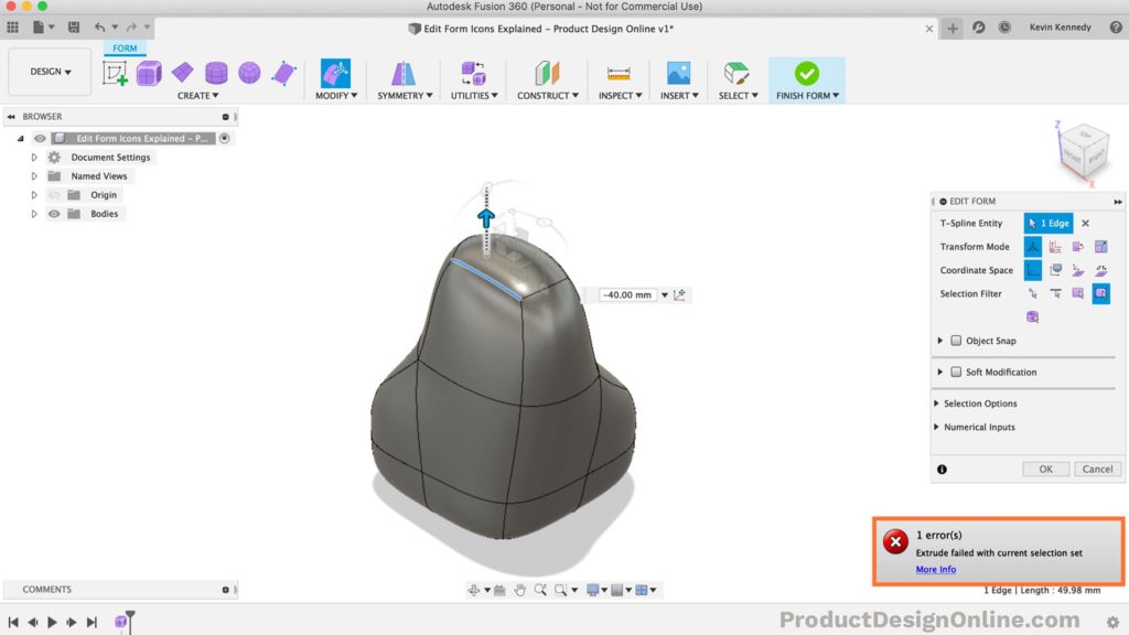
You can think of non-manifold surfaces as the geometry that cannot exist in the real world because they’re either not touching or have no (real) thickness to them. For example, if you were to select an edge on your sculpted form and hold down the option/alt key while dragging the single direction arrow… you’ll notice that you get the manifold error because you cannot realistically extrude an edge, as it wouldn’t have any thickness to it.
Leave a Reply