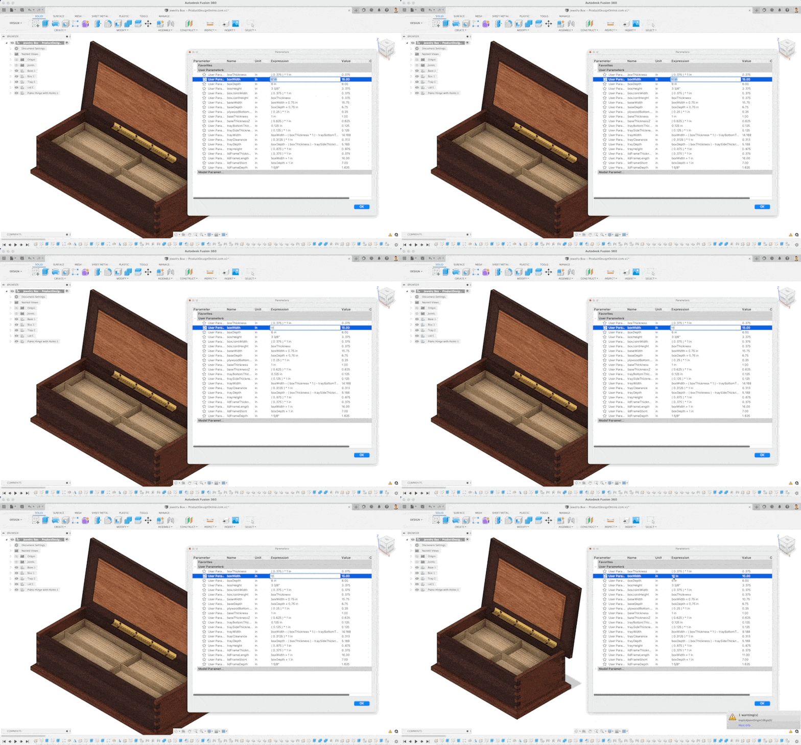
Control the size of objects in your Fusion 360 design with User Parameters. User Parameters allow you to create equations and relationships that you can reuse throughout sketch dimensions and modeling features.
User Parameters makes it easy and efficient to propagate size changes throughout the model, all from the Change Parameters dialog.

- Access Parameters Dialog in Fusion 360
- Create New Parameters in Fusion 360
- Create Users Parameters “On the Fly” in Fusion 360
- What Fusion 360 Parameters are available?
- 3 Advanced Tricks with Fusion 360 User Parameters
Access Parameters Dialog in Fusion 360
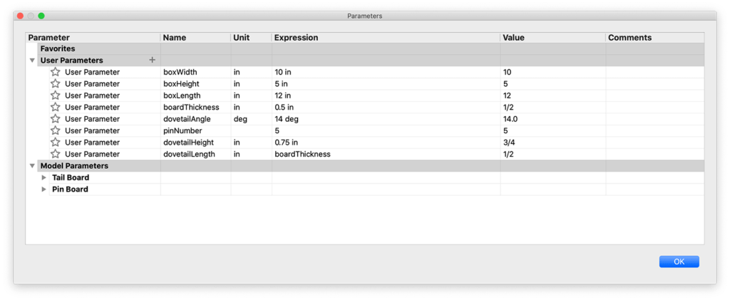
Access the Parameters dialog from the Design workspace > Modify > Change Parameters.

Create New Parameters in Fusion 360
In Fusion 360, you can create user parameters at the beginning or while working on your design file.
- Open the Parameters dialog. Design workspace > Modify > Change Parameters.
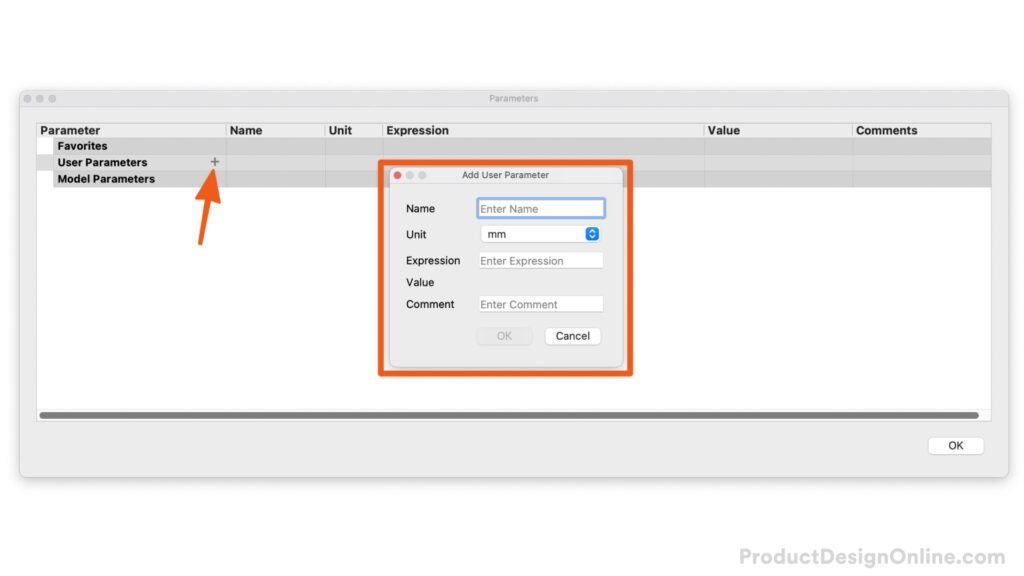
- Select the plus (+) icon, loacted next to the “User Parameters” heading.
- Define the Paramenter Name, Unit, Expression Value, and Comment (optional).
- Click OK. You can now use the parameter value with Sketch Dimensions and Model features.

Create Users Parameters “On the Fly” in Fusion 360
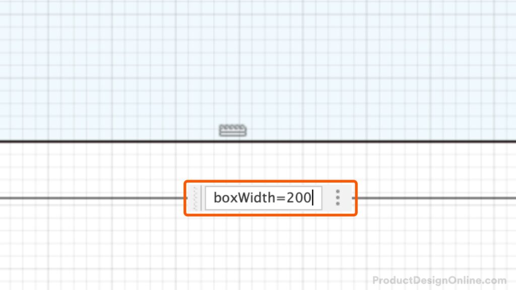
Create parameters “on the fly” while you type values directly in the input fields. This helps you create parameters without the need to open the Change Parameters dialog. Fusion 360 automatically adds “on the fly” parameters to your favorites, so that it is easy to find in the Parameters dialog.
Note: Parameters created on the fly are considered “Model Parameters” and not “User Parameters.” That’s because they’re derived from the model itself.
In essence, you can use model parameters and user parameters in the same manner – calling the parameter name in both sketch dimensions and modeling features.

- Within a dimension input (Sketch or Model feature), define the parameter name.
- After the parameter name, use the equal symbol (=) and the desired value.
Note: there are no spaces between the parameter name and equal symbol. You will also find that parameters created ‘on the fly’ do not show the parameter name after you save them. However, changing the original dimension will continue to update the parameter itself (and all areas you use the parameter).
What Fusion 360 Parameters are available?
Fusion 360 user parameters are extremely powerful and allow a number of different operations, equations, and functions – or a combination of each. The following operations, equations, and functions are available to use with Fusion 360 user parameters.
Order of Operations
| Operation | Symbol | Example |
|---|---|---|
| Parenthesis | ( ) | (sin(15 deg)) |
| Exponentiation | ^ | width ^2 |
| Negation (unary subtraction) | – | (-2.00 + length) |
| Multiplication or Division | * or / | sin(PI/4 rad) or (0.5 * base * height) |
| Addition or Subtraction | + or – | (-2.00 + height – 0.35 * base) |
Mathematical Constants
| Operation | Symbol | Example |
|---|---|---|
| pi, π | PI | (100mm/2*PI) |
Functions
The following functions are all available in Autodesk Fusion 360 to use with User Parameters.
| Syntax | Expected Types | Return Type |
|---|---|---|
| cos(expr) | angle | unitless |
| sin(expr) | angle | unitless |
| tan(expr) | angle | unitless |
| acos(expr) | unitless | angle |
| asin(expr) | unitless | angle |
| atan(expr) | unitless | angle |
| cosh(expr) | angle | unitless |
| sinh(expr) | angle | unitless |
| tanh(expr) | angle | unitless |
| sqrt(expr) | unitless | unit^1/2 |
| sign(expr) | unitless | any Return 0 if negative, 1 if positive |
| exp(expr) | unitless | any Return exponential power. For example, returns 2.688E43 for 100. |
| floor(expr) | unitless | unitless Next lowest whole number |
| ceil(expr) | unitless | unitless Next highest whole number |
| round(expr) | unitless | unitless Closest whole number |
| abs(expr) | any | any |
| max(expr1;expr2) | any | any |
| min(expr1;expr2) | any | any |
| ln(expr) | unitless | unitless |
| log(expr) | unitless | unitless |
| pow(expr1; expr2) | any, and unitless respectively Can construct unit valid equation that can go invalid “pow(3.0; d12)”. Decimal powers round at the eighth decimal place. | unit^expr2 |
| random() | unitless | unitless |
3 Advanced Tricks with Fusion 360 User Parameters
Learn how to create minimum and maximum user parameters in Fusion 360. You’ll also learn to automate rounding up to the desired fraction, and how to create parameters “on the fly” in Fusion 360.
Transcript
Three parameter tricks you wish you knew earlier.
Number one – use min and max values to ensure your parameters stay within an expected range.
Working on this tea kettle design, I don’t want it to be smaller than 170mm or larger than 200mm. Changing the parameter outside this range will break the model or make the model larger than desired.
Create a new User Parameter with your desired parameter name, and I like to add the word “Limit” to the end. For the value, we’ll start with “min()”.
The Min and Max functions require two expressions in the following format: min(expr1;expr2).
Inside the minimum, we’ll place the maximum value of 200mm, a semicolon, and then we need to define the minimum value within the max function. We’ll write “max,” and parentheses, followed by 170mm. Before the closing parenthesis, we need to define our user parameter that will rely on this min/max function. In this case, my kettleHeight parameter, followed by the closing parenthesis.
Note that the min and max values appear to be switched. Writing it this way ensures that anything over the maximum desired value will use the max of 200mm; while anything under the min value will use the minimum of 170mm.
Finally, edit the original parameter in your sketch or modeling feature.
Changing the parameter beyond the min and max will now prevent us from destroying the model. Notice how the parameter doesn’t update past the min or max value.
Number two – you can create parameters on the fly while defining sketch dimensions or modeling features. Simply type the desired parameter name, the equal sign, and the desired value. Note there are no spaces between these. This can save a ton of time compared to opening the Parameters dialog each time.
However, it’s important to note that this creates a model parameter and it will automatically be listed in the ‘Favorites’ section of the Parameters dialog. Parameters created on the fly will not be listed as User Parameters. This is because model parameters are derived from the model, while user parameters are created without a sketch or modeling feature. Both user parameters and model parameters are essentially the same and can reference one another.
The one downside to “parameters on the fly” is that the original dimension input will not indicate that it’s a parameter unless you hover over the value. If you change the original, it will allow you to update other dimensions, including sketch dimensions and modeling features.
For example, I can edit the wall thickness of the Shell command used in the creation of the Lid. Updating either the user parameter or the original Shell command will drive this value.
Number three – use parameters to round to a specific fraction. This one is for all the woodworking and CNC folks who work with stock that comes in increments of ⅛, ¼, or any other inch increment.
Start by setting up three parameters. “partLength” will represent the desired length of your final part.
A parameter called “Finish” will serve as the clearance or extra material you need for facing, sanding, or finishing the part.
Third, a parameter called “Rounding” will serve as the increment that Fusion 360 rounds to. This is the variable we’ll test at the end. I like to use Rounding as lowercase “round” is reserved as an expression that will round to the closest whole number.
You will then use the Ceiling function, written as ceil(). Within this, we’ll place the (PartLength+Finish)/Rounding). We’ll then place this entire thing within parenthesis so we can multiply it by Rounding.
Change the “Rounding” parameter to any desired fraction and the stock length will round up to it, regardless of your Finish parameter.
There’s a few more parameter functions available in Fusion 360, including “Random,” “PI,” and more. Check them out in the video description.
[Upbeat Music]
Special thanks to all the new Patrons and those who bought me coffee over the last few weeks. If you’ve learned anything with my videos, consider donating to my mission of making CAD education accessible to everyone.
Be sure to subscribe and check out this next video with workflows that you should know.
[End Upbeat Music]
Thank for this clear and easy briefing on Parameters. I have a follow up; Can you make some parameter “universal” across multiple designs? For example: I work in wood and I would like to enter the dimensions of a 2×4 once and have that be universal for all designs that use 2x4s
Hi Richard,
For something like a 2×4, you may be better off creating a 2×4 file and then inserting it into various designs as the ‘External Component’. You could then break the link and alter the length since the 2×4 dimension wouldn’t ever change.
If you were to do this with user parameters, you can use the Derive functionality as I cover here: https://youtu.be/VsqRV7JvBKc?si=VOMoT6djVrFY1YMP
The other option would be to use the newer ‘Configurations’ workflow.
Best,
Kevin
i’d like the spacing between features to follow a logarithmic pattern. I have try without success creating a parameter but cannot get it to evaluate properly…. Any ideas?
Hi Francois, Can you kindly share your Fusion file so I can take a look?
There are a number of factors to consider when dealing with parameters/patterns. It will be fast for me to help if I can see what’s going on 🙂
Regards,
Kevin
Hi Kevin, New Fusion user here and I’m having a few issues with formulas in parameters:
Can I use text values in If Statements? if(text=??;then;else)
The exponentiation function only seems to work on unitless values
I’m 67 and learned drafting on a board with T-Square, pencils, and scumx. I am fairly proficient with computer languages, but these two issues are not well explained in the help content. Thanks
Hi Bill,
You can use text values with the If statements as long as you set create them as parameters first.
For example, if you were to create a BookShelfHeight parameter you could use “if(BookShelfHeight < 500mm; 2; if(BookShelfHeight < 1200mm; 3; 4))" If the bookshelf height is less than 500 mm, it will have 2 shelves. If the bookshelf height is equal to 500 mm or less than 1200 mm, it will have 3 shelves. If the bookshelf height is equal to or greater than 1200 mm, it will have 4 shelves. Changing the value in for the BookShelfHeight parameter will drive the if equation. -Kevin