Generative Design in Fusion 360 uses computer algorithms to output potential design ideas based on manufacturing, materials, stress, and other requirements.
In this video, we’ll take a look at creating a chair and a shelf bracket using Fusion 360’s generative design workspace. The outcomes can be manufactured, including a 3D printable shelf bracket (that looks interesting).
Generative Design Chair
What if you could let the computer design the chair for you? After defining the minimum requirements – backrest, seat, and the four legs (feet) – generative design can be used to generate potential design solutions.
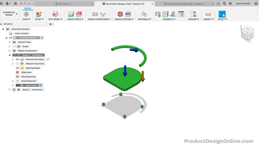
Preserve Geometry
I preserved the backrest, seat, and four legs (feet) of the chair. This is the starting point for all Generative Design projects.
Obstacle Geometry
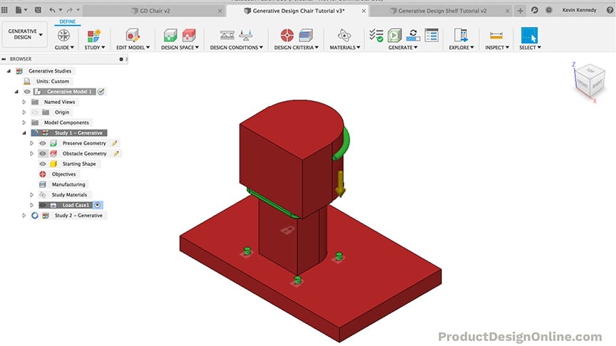
After defining the preserve bodies, you’ll want to define the obstacle geometry. The Obstacle geometry represents any areas that the computer algorithm shouldn’t use when coming up with design solutions.
For example, notice I blocked out the entire area above the chair’s seat (picture below). This ensures the seat is usable by telling the program that the design cannot obstruct that area.
The obstacle geometry below the chair’s seat is not required. This was simply a way of me telling the program that I only want the chair legs to be defined and attached on the outer areas of the seat.
Generative Design Results
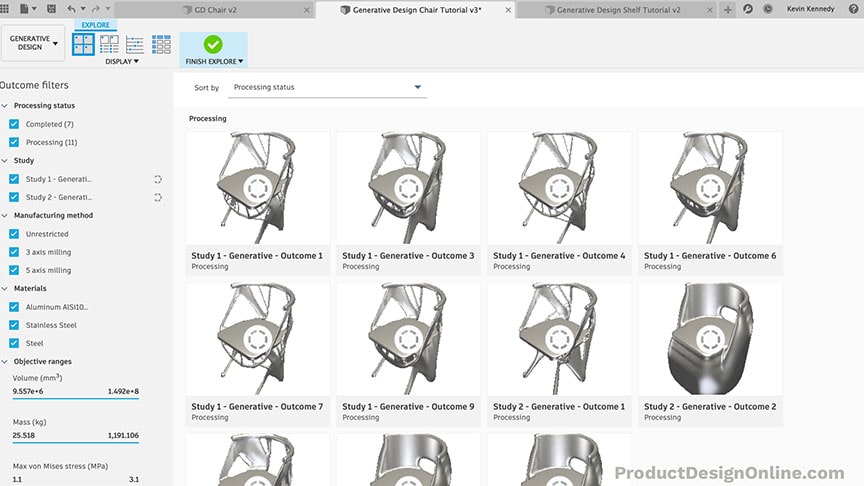
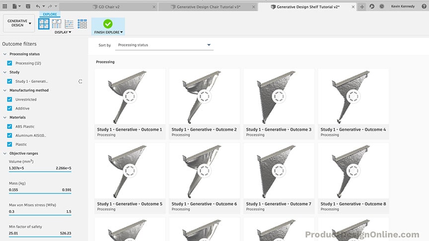
The number of potential design solutions you receive will depend on the number of materials and other requirements you define. You will be able to preview the solutions while they are still processing.
Notice the filter options on the left-hand side. You can use the filter options to narrow your design solutions to choose one that fits your requirements based on size, weight, volume, material, etc.
Final Generative Design Chair
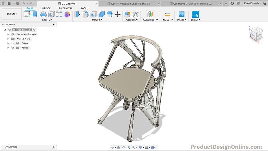
Results can be exported back to the Design workspace. Notice how the geometry is created with T-splines. This means you can edit the geometry in the Form (Sculpt) workspace.
You can also use the modeling tools to further develop or tweak your design as needed.
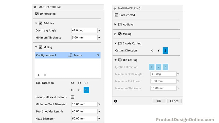
The design solutions are based on the manufacturing settings you define. In Fusion 360 you can choose between the following manufacturing settings:
- Unrestricted – doesn’t take manufacturing into account
- Additive – used for 3D Printing and other additive methods. Define the overhang and minimum thickness.
- Milling – used for any time of milling or CNC process. Define the axis type by selecting 2.5-axis, 3-axis, 5-axis, or a combination of the three.
- 2-axis Cutting – define the cut direction
- Die Casting – (currently in preview or beta mode) used to simulate die-casting metals. Define the ejection direction, draft angle, and minimum and maximum thickness.
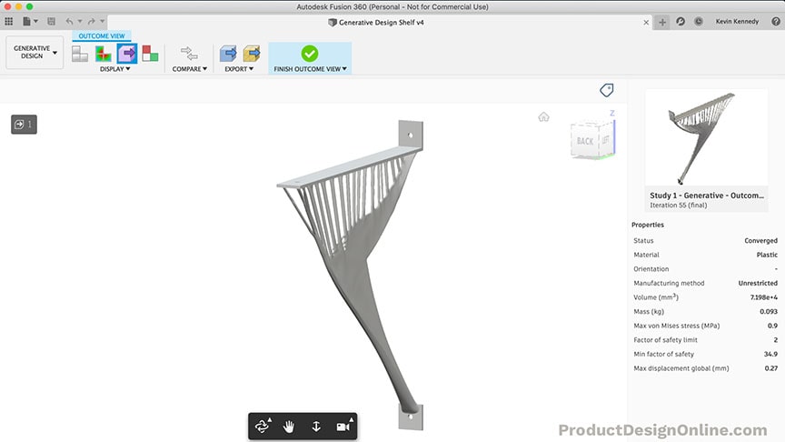
Generative Design Shelf Bracket
A shelf bracket comes in a handful of standard shapes. Using Generative Design one can look at alternative designs based on manufacturing and material requirements.
Check out this plastic shelf bracket that was created in Fusion 360’s Generative Design workspace.
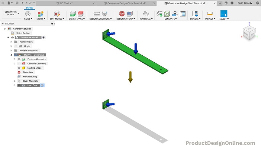
Preserve Geometry
I started with the bare minimum to generate shelf designs. Notice how I also added screw holes. You can use “Obstacle Connectors” to block out the screw and bolt holes.
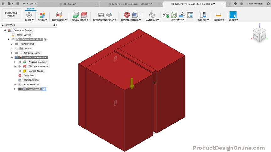
Obstacle Geometry
For the shelf study, I created a bunch of obstacle geometry bodies. Notice in the image below how I blocked around the entire object, forcing the algorithm to create solutions within the standard width of the shelf bracket.
Creating obstacle geometry or bodies is not required. However, in almost all designs you’ll want to define some areas as obstacles. Remember, the more you tell the algorithm, the more likely it is to produce satisfactory results.
Shelf Generative Design Solutions
Many of the shelf designs were nothing special. On the other hand, some provided a unique solution that minimizes the amount of plastic or material used.
Remember that generative design is not just about saving money in the manufacturing process. Minimizing mass is also better for our environment on many accounts – shipping, raw materials, etc.
Generative Design Workspace
The Generative Design workspace is normally only available to those using a commercial (paid) Fusion 360 license. However, until January 1, 2020, anyone with the Hobbyist or “Personal Use” license type can access and run generative design studies absolutely free.
The Education (student) license also offers free generative design. However, it is currently only available to the 200 Autodesk partner schools. Keep an eye out in early 2020, as it’s expected that Autodesk will release the Generative Design workspace to all students with an Education license.
Questions?
Don’t hesitate to comment your questions below!
Transcript:
Hey there, it’s Kevin Kennedy and welcome to another Generative Design video. In this video, I’m going to show you a few more tricks as we take a look at using Generative Design with a chair and a shelf bracket.
If you haven’t watched my first Generative Design tutorial then you’ll want to check that out first, as I won’t be covering all the basics of setting up the study.
I wanted to create a tutorial that was more practical in terms of how a hobbyist may utilize Generative Design, especially since my first tutorial was more focused on a mass-produced part.
I’ve gone ahead and set up the basic structure of a chair, as well as a shelf bracket. To satisfy the minimum requirements of generative design I’ve defined the backrest of the chair, the seat of the chair, and the starting point of all four legs.
I’m going to enter the Generative Design workspace by selecting it from the workspaces dropdown.
Our study number 1 is then automatically created. We’ll first need to preserve all of these parts so they’re included in the results.
One trick while trying to preserve parts is that you can simply drag over all of your parts to quickly select them all. If you have “obstacle geometry” you’ll want to deselect them or hide them before doing this.
I only set up the minimum requirements for generating a chair, so we’ll still need to create the obstacle geometry. One thing that I didn’t show in the last tutorial is the fact that we can create obstacle geometry using the “Edit Model” feature. The difference is that anything created in the edit model space, will not appear when you’re back in the design workspace. So this is a great way to set up obstacle geometry as you work on creating your Generative Design study.
The most important thing with this chair would be for us to block out the entire area above the seat, which will tell the algorithm that it can not use that space for any of the design solutions.
I’m going to create a new sketch off the top of the seat. Then, I’m going to project the body geometry of the backrest, so I can create a profile shape that’s the entire area of the seat, including some extra room for clearance.
I’ll use the line command to close off this shape so I’m able to extrude this closed profile.
The key thing with the extrusion is that you’ll want to make sure your operation is set to “new body” so this doesn’t join the seat body. It’s crucial that this is a separate body so we can turn this body into obstacle geometry.
With this particular design, this is the only obstacle geometry that would be required. However, one of the core principles of generative design is understanding the more you tell the algorithm the more predictable the outcome will be.
To further define the chair’s geometry we may consider adding another obstacle body below the seat.
I’ll simply offset the bottom perimeter of the underside of the seat. This will let me create an extrusion that runs from the bottom of the seat to the bottom of the chair legs, by using the “to object” extent type. Again, I’ll make sure that this is a “new body,” so we can differentiate this body from the preserved bodies.
What this obstacle geometry would do is tell the algorithm that the legs of the chair must be defined around this space, and they can only attach to the bottom of the seat where the open areas remain.
After running this first study, we’ll clone it and I’ll remove this body so we can see how different the outcomes can be by creating only one extra body.
Lastly, I’m going to create a sketch on the bottom of the chair legs. I want to tell the program that no geometry can run past the bottom of these legs, which will ensure the chair remains flat on the ground.
Now that I’ve created all of the bodies to be used as obstacles, I’ll select the “Finish Edit Model” button.
To select all three of these bodies I’ll hide the preserved bodies in the browser and I’ll drag over them in the canvas window. You can then select the Obstacle Geometry button in the toolbar, and notice how the 3 bodies are selected so all we have to do is click “OK” or hit the enter key on our keyboard.
Watch what happens as I switch back to the design workspace. You’ll see the obstacle bodies no longer appear since we created those in the Edit Model mode within the generative design workspace.
Back in the Generative Design workspace, the next requirement would be to add structural constraints. To do this, we’ll need to hide the obstacle geometry and turn the preserved geometry back on.
One of the easiest ways to think about the structural constraint is to think about what part of the model will touch something while it’s in use. The bottom of our chair legs will be touching the ground, so we’ll need to apply fixed constraints to all four of them.
We then need to define the structural loads or forces applied to the object. With our chair, we’re going to have weight placed down on the seat as well as some weight or force towards the backrest.
I’ll first select the top of the seat. I’ll also change the units to ounces, so it’s easier to imagine the amount of force. I’ll type out 3200 ounces or 200lbs of force.
I’ll use the marking-menu to repeat the structural loads command and this time I’ll select the backrest body. Our force is likely going to come more from an angle than straight back, so we can use the rotation slider to add about 20 to 35 degrees to the force.
For this one, I’ll change the units to ounces as well, and then I’ll type out 1600ounces or 100lbs.
For the design objectives, we want to double-check that our setting is on the default of minimizing mass, which will tell the algorithm to use the least amount of material possible while fulfilling all of the other requirements.
For manufacturing, I’m going to keep unrestricted checked.
I’m then going to uncheck everything else except milling. Within the milling section, I’ll also add the 5-axis milling option, so we can compare what the outcome may be with 3-axis vs 5-axis. For the sake of simplicity, I’m going to leave the tool properties as the default values. But note that you would need to fill out the values of your machine’s tool.
Lastly, we will want to define our materials for the chair study.
We can leave the default of aluminum. I’m also going to stainless steel and steel to the top of the material’s list. Keep in mind that for every material you add that’s going to generate more outcomes per all of your other requirements. Generally, I would recommend that you pick no more than 2 or 3 materials per each study, or it’s going to take a long time for everything to process.
Once the materials are selected, we’ll need to turn the obstacle bodies back on.
The “Pre-check” button now has a green checkmark, which means we’re ready to run the study, and we don’t have any concerns.
While the program is processing the designs of this first study, I’m going to hit the “Finish Explore” button and I’m going to clone the study, so we can run a second without the obstacle underneath the chair.
If you right-click on a body you can select “Clone Study” which will copy everything over to Study #2. I’ll edit the Obscable geometry and then I’ll simply deselect the bottom body so we can generate results where the chair legs can intertwine or connect anywhere underneath the seat.
We can also hide the body to remove it from the canvas window.
I’ll leave all of the other settings the same, and I’ll generate study #2 so we can compare the results with the first study.
While the chair results are processing, let’s set up a study for a common shelf bracket.
I thought something as simple as a shelf bracket would be a great starter project for those of you that are into 3D printing.
I’ve gone ahead and set up the minimum requirements of a simple shelf bracket. You can see the two holes and parts of the bracket that would be required to attach this to a wall. I also have the straight piece where the shelf would sit, with an additional hole to secure the shelf to the bracket.
Similar to the chair design, we’ll need to define obstacle boundaries after entering the generative design workspace.
First, I’m going to select both components so I can preserve them.
I’m also going to add the fixed structural constraints where the shelf would need to be attached to the wall.
Once again, I’ll edit the model, to create obstacle boundaries that are only included when this design file is viewed in the Generative Design workspace.
I’m going to create a sketch off the back of the bracket, where it’s attached to the wall. I’ll then create a 2-point rectangle that encompasses the entire object, ensuring that nothing is generated behind the brackets. This will make sure we have a smooth surface to attach the bracket to a wall.
If you remember in the chair example, we did the same thing by creating a box below the bottom of the chair legs.
I’ll just extrude this out to an arbitrary number and then I’ll click “OK”.
Another area that we certainly do not want any geometry generated would be the top of the shelf bracket, where the actual shelf would sit.
Therefore, I’ll create a sketch on top of that.
I’ll hit “E” for extrude, and I’m going to extrude the entire surface up until its well over the back part of the bracket. As we did with the chair example, remember that you’ll need to select “New Body” as the operation type.
The very last area that we would need to clear would be the screw holes for the bracket.
Instead of creating another block, we can use Fusion 360’s built-in “connector obstacle,” which is located in the toolbar.
The connector obstacle lets us define where bolts and screws would go. You’ll see that we first have to select the “Start of Shaft”. In our case, this would be the circle at the start of the hole. For the end of the shaft, we would need to select the circle on the other side. Notice how this automatically fills the shaft diameter and shaft length to their respective values.
If we didn’t select them we could define them by simply typing out or desired value.
Next, we can create the bolt or screw head, by turning that selection on.
You’ll see that you are also given the options to define the diameter and length of the head, as well as the ability to flip the bolt head to the other side or to add it to both sides.
Before clicking “OK,” we’ll also want to turn on the “Tool Clearance” option. This will let you extend the body out from the bolt or screw head, to define the clearance required to tighten the screws. In our case, we would want to drag this out to ensure there is enough room for a screwdriver or drill to screw this bracket into the wall stud.
I’ll make the length of the tool clearance 200mm before clicking “OK”.
We would also need to create the same “Connector Obstacle” for the hole on the top of the bracket, so we can secure the shelf to the bracket.
At this point, we’ve defined the spots that are required to make sure this shelf bracket remains functional.
Similar to the chair, we may also want to define additional obstacles, as a way to further predict the types of outcomes we should expect.
If we want to keep the shelf’s entire width defined by the top of the bracket, then we could create a box on both the left and ride sides.
To do this, I’ll create a new sketch on the back surface. Then, I’m going to project the outer geometry as well as the top bracket geometry. This will let me use the geometry to create straight lines, on each side of the bracket.
We can now extrude each rectangle, essentially creating walls on the side of the bracket, to tell the program that we want the design solutions to remain completely within this void.
I’ll finish editing the model and let’s turn these into obstacle geometries.
We can now hide the preserved bodies so we can select all of the remaining bodies to be applied as obstacle geometry.
Once the obstacle geometry is defined we’ll need to define the structural loads of the bracket.
We first need to apply a force pushing down on the shelf, where the weight of the books or objects would go. Intending this for 3D printed plastic, I’m going to add a force of only 160ounces or 10lbs.
Our shelf bracket would also have additional forces pushing towards the wall. However, I should state that this is not my area of expertise. I’m curious what you guys think…so comment below the location and amount of forces that you think a standard shelf bracket would have.
For this tutorial, I’ll simply add an additional 10lbs of force going at a 30-degree angle to both areas where the screws would go.
For the manufacturing settings, I’ll leave unrestricted checked and I’ll make sure additive is checked, but nothing else. I’ll also up the minimum thickness of additive to be 5mm.
For the materials, I’ll add ABS Plastic and the general “plastic” option to the materials list. I’ll also leave the default of aluminum to see how different that comes out in comparison to the plastics.
Once the materials are added, we simply need to turn the obstacle bodies back on and we’re ready to run the study.
While the shelf brackets are processing, let’s take a look at some of the Chair results.
At first glance, it appears that about half the designs came out very interesting, while the other half are essentially big blobs or blocks of steel.
Remember that we also ran two studies, the first which restricted how the legs attached to the seat, and the second, which gave the program free range to use the space under the seat.
Let’s compare one of the designs from each study.
If I look at the bottom of the chairs, you’ll see that defining just that one body underneath the seat made a huge difference in the outcomes. If there’s one thing that you take away from this tutorial it’s the fact that the more you tell the program the more predictable your results will be.
I’ve gone ahead and cut out the wait time for the shelf brackets so we can take a look at those results.
Similar to the chair design, it appears that some of the results didn’t come out so well. On the other hand, some of them look pretty interesting, and could definitely be 3D printed.
One thing to point out, I should’ve put a “connector obstacle” on the top hole, as it appears it was filled in on most results. This isn’t a huge problem, as we could always add the hole after exporting the result. Just keep this in mind, as you’ll see little things like this will start to add up and affect the outcomes of your designs.
To summarize this video, I want to clarify a common misconception with generative design. Many people have this false perception that you simply tell the program to create a chair and it will come up with thousands of ideas.
You can think of generative design as a game of connecting the dots. You need to define where the dots are placed, and the computer will output as many solutions possible based on the defined requirements. The computer, however, will not change the placement of the dots.
Looking back at the chair example, you can imagine how different the outcome would be if I had designed a different style backrest or shape of the seat. Remember, that was me defining the dots for the program to use.
The outcomes would also be quite a bit different from plastic or other materials that aren’t as strong as metals. Ultimately, the more you can tell the program the more likely it is to produce a satisfactory result.
Last but not least, I want to give a shoutout to all the new Patrons and the supporters who have bought be a coffee over the last few weeks.
Special thanks to the new Patrons…
BC Designs, Andrew Burda, Brian Ingram, and Dennis Johnson
Also, thanks to those who supported the channel via my Buy Me a Coffee page…
Dennis Murphey, The Modifier, Michal D, Steakbroetchen, J Bonn, @AIK162, Geoff, and Anonymous.
If you have found my tutorials to be helpful in any way then consider supporting my content by becoming a Patron or by making a one-time donation on my “Buy me a Coffee” page. All of the contributions help me keep the website up and running and will help me continue to create high-quality tutorials.
As always, I truly appreciate you taking the time to watch this tutorial. Click that thumbs up icon if you learned something in this video and be sure to click that playlist in the lower right-hand corner to watch more generative design tutorials.
I have a question how do I get the sketch before edit or doing the generative design
Hi Jonnathan,
Apologies, I’m not following your question. What object are you trying to design with Generative Design?
Cheers,
Kevin