This tutorial highlights the common steps taken for digital fabrication projects. We’ll look at the features used to create a sculpture that was created by the Norwegian artist, Magnhild Øen Nordahl.
She has some incredible work and often uses Fusion 360 to 3D Model her ideas before cutting them out on a CNC.
Check out Magnhild’s website to learn more about her and her work.
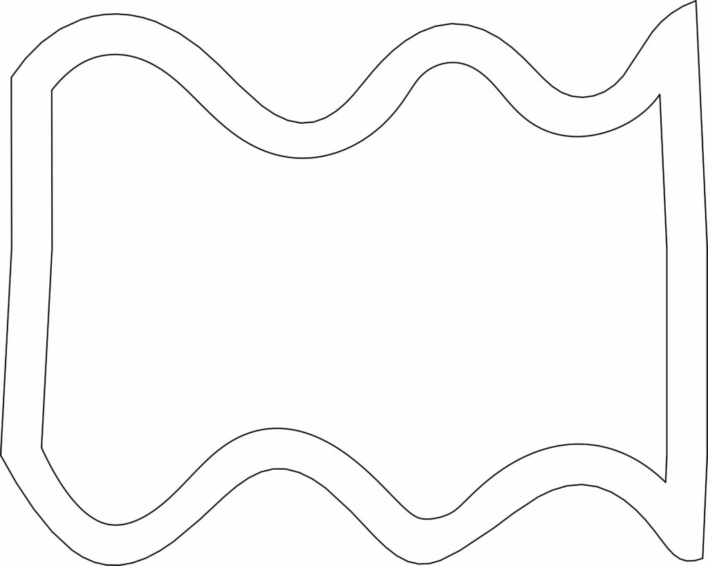
Reference Image
Looking to follow along? Download the reference image that I used in the tutorial.
Tool Library
Looking to use the same tool library that I referenced? You can click this link to download the tools.
How to import Tool Library in Fusion 360
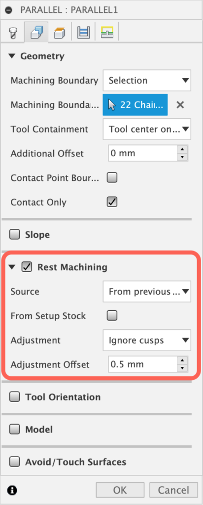
CAM Settings – Rest Machining
The CAM portion of this tutorial was covered on a very basic level. Understanding all of the available settings will allow you to create faster and more efficient tool paths.
Checking the Rest Machining option (located in the Geometry tab) will let you set the paths to avoid any areas that were carved out by previous paths. This typically cuts down the machine travel time, resulting in more efficient tool paths.
I’ll be releasing CAM tutorials on my YouTube channel very soon! Be sure to subscribe so you get notified!
Transcript
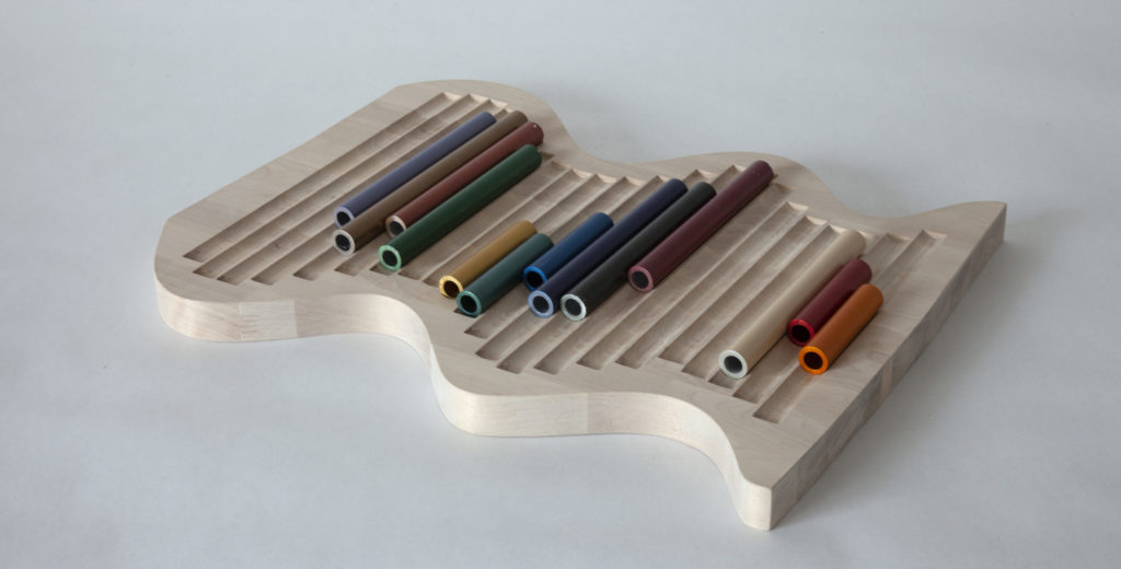
Let’s take a look at how to model your very own sculpture that can be milled on a CNC.
Hey there, it’s Kevin Kennedy, and welcome to this tutorial where I’ll walk you through how to create this object created by the Norwegian artist Magnhild Øen Nordahl.
The goal of this video is to create a simple 3D object that can be customized and then we’ll take it into the Manufacture workspace to set up the CAM tool paths.
We’ll take a look at attaching a reference image, creating simple 2D Sketches, the Extrude feature, creating patterns, and we’ll set up 3 different tool paths with the Manufacture workspace.
Let’s start by creating a new component, which will help us organize all of the features.
Simply select the New Component feature in the toolbar. You can type out a name, such as Sculpture, followed by the OK button.
A lot of digital fabrication projects start with initial ideas in your notebook. Fortunately, we can use reference images to help us recreate objects in Fusion 360.
Check out the link in the video description if you want to grab the same reference image that I’ll use. Otherwise, I encourage you to customize the shape to make it your own. You can even proceed without a reference image and simply use Fusion 360’s native sketch tools.
To add the image, we’ll select the Canvas feature in the toolbar. With the “Insert from my computer” option, we can select the image from our local folders.
We’re then prompted to select an origin plane. These origin planes correspond to the X, Y, and Z coordinates, which represent our 3-dimensional space. Generally, you’ll want to select the plane that represents how the object will sit in real life. We can select the bottom XY origin plane since this object has a flat bottom that rests on a table.
You’ll then see that the reference image may be too small. We can simply drag the corner scaling icon to make it larger. We’ll take a look at calibrating the image to the correct size, but for now, let’s click the OK button.
On the left-hand side, you’ll see what’s called the Fusion 360 Browser. This represents our file structure. Here, we’ll find the new component which we created at the beginning. Remember, I mentioned this component will organize our assets.
If we toggle open the component, we’ll find a Canvases folder. We can toggle that open, right-click on the image, and select the calibrate option.
This lets us define two points and then the distance between the two points. When working on projects that you intend to mill, you’ll want to keep in mind the size of the material you have. This calibrate option is a great way to ensure we design our object with the material size in mind.
I’ll simply select these two points on the left. Notice how a dimension input now appears. I’ll enter 280mm for the length, followed by the Enter key. Notice how the image immediately resizes to the appropriate size.
We’re now ready to trace the reference image with a 2-dimensional sketch. In Fusion 360, most designs start with a 2-dimensional sketch, and then you’ll turn them into 3-dimensional bodies.
You’ll find a Create Sketch button in the toolbar. Once again we need to select an origin plane, so let’s select the same one since we want to trace this image.
We’re then placed in the sketch environment. This gives us access to all the 2-dimensional sketch features.
Let’s start by tracing the line on the left.
We can activate the Line feature in the toolbar. We’ll need to click once for the first point, followed by clicking a second time for the other endpoint.
Remember that reference images can be a great starting point and that you don’t need to trace them one for one. In fact, most of the time you’ll want to tweak your design once you’re looking at it in 3-dimensions.
Once the line is complete I’ll hit the escape key
We can then do the same process on the other side.
It’s important to note that if your mouse is trying to snap to the grid then you can turn off the “snap” option in the Sketch Palette.
You may also find it hard to see the sketch geometry with the reference image. In the Browser, we can right-click to select “Edit Canvas”. We can then lower the opacity and click OK.
To trace this interesting curvature we can use the Fit Point Spline tool. You’ll find it in the toolbar or the Create dropdown.
We’ll start the spline by selecting the endpoint of our line on the left. Each time we click with the spline tool we create another spline point. We’ll want to click at each peak or vertex of these curves, minimizing the number of points we use.
We’ll also want to make sure we end the spline by snapping to the line on the right. Notice that you either have to select this green checkmark or hit the enter key, to complete the spline.
I’ll follow the same process for the bottom spline. After that’s complete we’ll take a look at fine-tuning the spline handles so the spline matches the reference image.
Now that both splines are complete we can adjust these green spline handles. These handles give us control over the curvature of each spline point.
You’ll first want to hit the escape key to clear all commands. We can then simply click and drag on the spline handles to position them so they better align with our image.
Notice that you may have to select a spline point to get it’s spline handle to appear.
Of course, we’ll want to follow the same process for the bottom spline.
You may have noticed that once we completed our second spline that our shape got this light-blue background.
That means we have a closed profile shape, which is required to turn a 2D sketch into a 3-dimensional body.
In the toolbar, we can select the SOLID tab. It’s here that you’ll find one of the most used features, which is called the Extrude command. This extrude command lets us simply drag the blue arrow or type out a defined value to turn our 2D sketch into a 3D body.
Again, remember that you want to keep in mind the project materials that you’ll be working with, along with the limitations of your CNC machine.
I’ll type out a distance of 30.5mm, followed by the OK button. We now have a 3-dimensional body. We can continue to shape this body by adding more sketches to add or cut away more 3D bodies.
Looking at the final images, you’ll see that she milled out these nice cavities where the pipes can lay.
It’s important to note that with any 3D modeling program there are often many ways to achieve the same results. Ultimately, you wanna choose what the most efficient option is while keeping in mind Fusion 360’s best practices.
There are several ways that we could do this part of the model. However, let’s follow the same steps to ensure that we cover everything she did to create this piece.
You’ll notice that the cutouts don’t run to the center of the pipe. That means we need to create a sketch above the top of our existing surface.
To do this, we can create a construction plane that will let us sketch above our existing body.
Select the offset plane feature in the toolbar. We’ll select the top surface, and then we’ll offset this 5mm.
At this point, we can right-click on the construction plane to select “Create Sketch.”
Thinking ahead, we want to create a bunch of straight lines, which we’ll reference with the pipe command. If you look at the design [Image] you’ll notice the pipes are offset from the outer edge.
We can use the offset sketch feature, however, we first need to have some geometry in the active sketch.
Instead of retracing our outer shape we can use a feature called “Project”. While in the sketch tab, you’ll find the Project command in the create dropdown.
Simply select the 3D body and click OK. You’ll notice that it traces the edge lines of our existing 3d body and Projects them to our current sketch, hence why it’s called the project command.
We can now use the offset tool, select the projected geometry, and we can drag this slider to position how far the geometry is offset.
We can either eyeball the offset based on the reference image, or we can type out a specific distance, such as -30mm.
We’re going to need a straight line for the pipe command to reference, so once again we’ll use the line tool.
This time, I’ll draw the first line, while making sure it extends past the highest point of each curve. You’ll also see that a parallel constraint appears, making sure the line snaps in parallel to the line on the left.
You’ll see why I’m doing this in just a minute.
Instead of manually drawing several more lines we can use a pattern feature. You’ll find the rectangular pattern feature in the Create dropdown.
Simply select the line and drag the blue directional arrow to the right. We can then change the Distance type to spacing. This lets us define the distance between each line.
I’ll then change the distance to 20.5mm.
We want the lines to go all the way to the right edge, so I’ll change the quantity until they do so. It appears that 22 will take care of it.
After clicking OK, we can click and drag on one of the lines to reposition it.
Right now our lines go past our offset shape. We can use the trim tool to fix this.
You’ll see the ends turn red and they’ll trim away to the nearest intersecting geometry. A time-saving trick with the trim tool is that you can click and drag through lines. Notice how that lets us trim away the lines a little bit faster.
We’ll continue this process on the top and bottom until all the lines are trimmed away.
If you accidentally trim away the spline then you can hit the undo button in the toolbar.
We can now head to the Solid modeling tab.
From here, we’ll find the Pipe command in the create dropdown. The pipe command lets us simply select a line to turn it into a pipe-like shape.
I encourage you to make your design unique by playing around with the size and dimensions.
For this design I’ll use the default of a round tube, with a 20mm diameter. I’m using 20mm because this particular sculpture holds these colored aluminum tubes with those measurements.
Notice how the feature defaults to the cut operation, which is why the geometry is red. This will cut the shape away from the existing 3D body.
I’ll click OK to look at the cavity.
Fusion 360 will automatically hide a sketch after using a modeling feature. We’ll have to turn it back on in the Browser.
We can then repeat this Pipe process to create a cavity per each of the remaining lines.
[Speed up Video, Skip to Pipes being complete]
Once the pipes are complete, we can turn off the sketches and reference images. We’re now ready to enter the Manufacture workspace to set up a CAM file.
We need to change our workspace from Design to Manufacture, using the dropdown list in the upper-lefthand corner.
I should note that the Manufacture workspace has a lot of settings and I’ll just be covering the common workflow you’ll need for a design similar to this. I won’t be covering everything in great detail. Be sure to comment below the types of projects you would like to CNC, as I’ll be starting to release Fusion 360 CAM tutorials in the coming weeks.
The first thing we need to do is define the machine, model orientation, and the size of our stock, which is the material that we’re going to cut.
Select the Setup icon in the toolbar.
We can first select a machine from the list of predefined machines. Otherwise, you can create a new profile that matches the details of your machine.
We’ll leave the operation type to Milling since we’re going to mill or cut away the wood.
You’ll then see that we can define the Work Coordinate System or WCS for short. This lets us reorient the part based on how we need to mill it. We can leave this to the default since our part is already in the correct orientation. Note that you can also change the box point by simply selecting another point. For example, we can change this to the corner. This serves as our origin or starting point.
Lastly, you’ll see that Fusion 360 automatically detects the body that we want to mill since we only have one 3-dimensional body in the model.
We can now define the size and thickness of the material. After selecting the Stock tab we first have to define the mode. You’ll see that we have several options to choose from.
If you have a board in hand then you can select the Fixed Size Box. This will let us define the actual dimensions of the board.
Contrary, if we plan on cutting stock just big enough for the part and vise, then we can select the Relative Size box. This lets us simply define an offset, making sure we have enough space around the part.
For example, I’ll set the offset to 40mm, leaving us with room to screw or clamp the board into the spoil board. Notice how we can set the round up value so our board doesn’t result in a strange dimension.
If your material is already the correct thickness then we can also change the top Offset to 0.
We can then click OK.
We’re now ready to create our first tool path to mill the inside cavities.
You’ll see while we’re in the Milling tab that Fusion divides features up into different categories.
Let’s start by carving out this 3-d cavity where the pipes rest. We’ll need to use a 3D path, since the geometry is 3-dimensional. Looking at the list of options, you’ll find the Contour option to be great for our need, given the steep curvature.
We’ll first have to define our tool. Again, a countless number of features and details can be defined, so for the sake of this tutorial I’ll select the preset 19mm round nose. I’ve included links in the description to the tool library so you can import and use the same tools.
Because we’re working with wood we want to make sure to disable the coolant.
We can then head to the Geometry tab. We’ll want to change the machining boundary to the “Selection” option. This allows us to select each edge of all 22 cavities that need to be carved out.
We can then click OK.
If we right-click on the tool path in the Browser we can select the Simulate option. This lets us preview the tool path to ensure it’s doing what we expect.
At this point, our paths are just “roughing passes,” which means we’re just clearing out the general material. We now need to go back in to clear out the remaining corners which weren’t cut due to our bit size.
For this, we’ll use the 3D path called “Pencil”. This path type helps us clear out internal corners that have fillets with small radii.
For this tool I’ll select the 3mm flat tool from the Tool Library.
Once again we need to select all of the contours of each cavity.
After the tool path processes, you’ll see that it cleans out the ends of each cavity, resulting in a better finish.
Lastly, to finish off these cavities we’ll need to create a finishing pass, so the wood results in a smooth surface.
For finishing 3D contours, a great option is the Parallel Path.
With this path, we’ll select a smaller 3mm tool size, which will help us achieve a smoother surface.
We can then select all 22 of the contours for the Machining Boundary selection.
After clicking OK, we can simulate the entire setup to make sure it will clear out the material.
Now that our cavity cutouts are complete we need to create a contour cut. This will allow us to cut out the outside shape.
With the 2D Contour path, we’ll select the 8mm flat bit. Of course, we’ll once again disable the coolant option.
Under the geometry tab, we’ll need to select the contour. In our case, we want the entire shape to be cut out, so we have to select the bottom edge.
One important concept when milling the contour of a shape is the use of Tabs. Tabs allow us to cut out almost all of the material while leaving small tabs that attach the object to the rest of the raw material. This ensures our part doesn’t detach on the final cutting paths, resulting in the bit accidentally running into it.
We can simply check the tab option and we’ll leave the settings to the defaults. Notice the tabs that now appear in the preview.
Lastly, our material is too thick to cut in one single pass. We’ll need to go to the Passes tab. It’s here that you’ll find the section titled “Multiple Depths.”
Let’s change the “Maximum Roughing Stepdown” to 4mm. This will tell the program that it should only cut 4mm into our wood for each pass. It will then automatically determine the number of passes required to cut through the stock.
Let’s click OK and take a look at the tool path.
You’ll see there are several lines on the side that represent each pass needed as it steps down further into the wood.
Once all of these tool paths are set up you’d be able to generate the code to run them on your CNC machine. It’s important to note that any red errors in the simulate preview should be looked at before you run any real-life cuts.
To summarize this video, we looked at creating a sculpture piece by tracing a reference image, while creating a 2D sketch with some simple sketch geometry. We then turned the 2D sketch into a 3D body, which let us further define the shape by cutting away some of the 3D material.
Once the design was finalized we were able to set up some simple tool paths in the Manufacture workspace. That would allow us to mill the wood piece on a CNC machine.
This digital fabrication workflow can be followed to create endless designs, with the only limitation being your creativity!
I’ll be starting to do more in-depth CAM tutorials very soon…so be sure to subscribe right now and hit that bell icon so you get notified!
Fusion 360 can be used for just about any digital fabrication project. This project looks at a piece created by Norwegian artist, Magnhild Øen Nordahl.
We’ll take a simple reference image and turn it into a 3D body, followed by using the Manufacture workspace to set up some simple tool paths for a CNC.
This video is a great overview of a workflow that can be used to create your own unique objects, but note that it does not cover every detail of the CAM environment.
Leave a Reply