Intro – Exercise File for this Tutorial
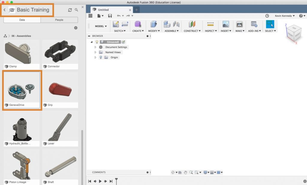
For this tutorial, I’ll be using a sample file located in the Fusion 360 data panelOpening The Data Panel gives you access to your Project Files and Folders. Click the Show Data Panel button in the upper left of the Fusion window. The Panel will expand on the left side and display the project folders. You can also add members to projects and Import data from other sources. More.
- Open the data panel by clicking on the grid icon in the upper lefthand corner.
- Scroll down until you see the “Samples” section.
- Double-click on the “Basic Training” folder.
- Scroll down and double click on the folder “#6 – Assemblies.”
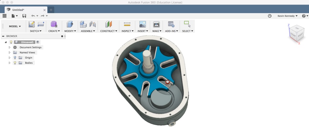
- Within the assemblies folder, you’ll find a “GenevaDrive” file (near the bottom of the list). Double click on the file to open it.
Sample files are “read only” files. You’ll have to make a copy of the file before you can do any work to it. To make a copy simply go to file > save asAllows you to rename a file and save a duplicate to an alternative location. More > and then you can rename the file. You also have the option to change the location of the copied file. Once you hit that blue save(keyboard shortcut CMD/CTRL+S) Saves the file that is currently open. More button the file will be duplicated and you can now make changes to it – let’s get started!
1. Analyze the Current Model and Its Timeline
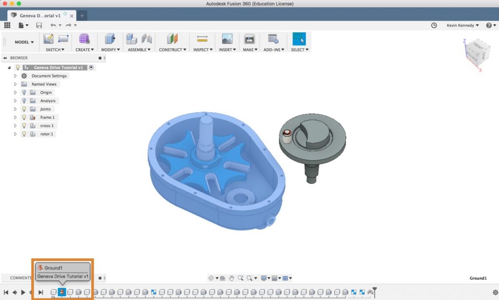
You’ll want to look over the sample file before you begin. This will help ensure that you apply joints and motion without any problems.
Start off by looking at the timelineThe timeline lists operations performed on your design. Right-click operations in the timeline to make changes. Drag operations to change the order they are calculated. More. Toggle open the folder by clicking on the plus icon.
Now that the timeline is expanded you’ll see that the frame component has previously been grounded. This is signified by the red “grounded” glyph in the timeline. The fact that the frame is grounded is a good thing – you won’t have to worry about it moving.
Next, always be sure to analyze any joints that are applied. If you click on this first rigid joint(keyboard shortcut “J”) Positions components relative to one another and defines the relative motion. Select geometry or joint origins to define the joint. Specify the type to define the relative motion. More you’ll see that it has been applied to the frame. You can also selectThe selection mode controls how objects are select when you drag in the canvas. More the other two rigid joints in the timeline and see where they’re applied.
It looks like this sample has the “cross” component jointed to the “frame” component. If you click and hold down on the “cross” component you’ll be able to move it around its revolute joint. It has enough joints applied that it’s not going to go anywhere.
Contrary, the “rotor” component still needs to be assembled. If you click and drag you’ll notice that you can move the rotor around freely, including all of the components in its subassembly.
2. Add Rigid As-Built Joints to the Rotor Subassembly
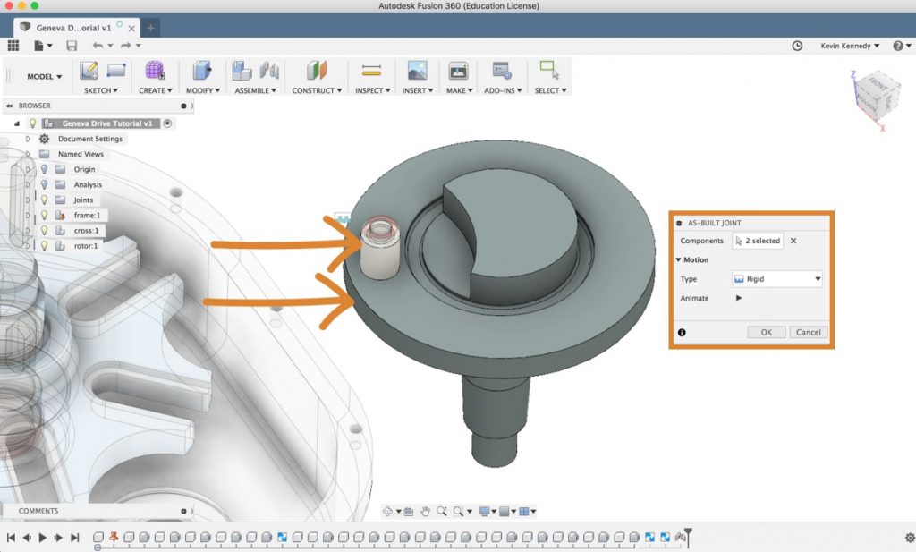
Before you add an As-Built JointPositions components relative to one another and defines the relative motion. Components maintain their current position. Select components to join. Specify the joint type and the position of the joint origin. More you’ll want to click “revert” in the toolbarUse the Toolbar to select the workspace you want to work in, and the tool you want to use in the workspace selected. More. This will revert all of the components back to their original position. Then, zoomZooms in and out as the mouse is moved from left to right. More in on the rotor so you can see all of the components in the subassembly.
You’ll need to add a few “rigid” as-built joints to all of the components in the rotor subassembly. This will help ensure they don’t lose their position when you go to move the main rotor component. You can think of the rigid joint as gluing two parts together.
Select “As-built Joint” from the assemble dropdown menu. We’re using an “As-built Joint” instead of a “Joint” because our components are already in place.
In the “As-built Joint” dialog boxCreates a solid box. Select a plane, draw a rectangle then specify the height of the box. More you’ll see that you have to select the two components you want to be joined. First, select the main rotor component and then select the white cylinderCreates a solid cylinder. Select a plane, draw a circle then specify the height of the cylinder. More component. Click okay in the dialog box.
Right-click and select “repeat as-built joint” and then select the white cylinder and the component just above it. Click okay in the dialog box.
Right-click once again and select “repeat as-built joint.” This time you’ll want to select the gray component and the red component and click okay in the dialog box.
Lastly, right-click to select “repeat as-built joint” one final time. Then, select the red component and the center cylinder component and click okay in the dialog box.
Now try to move the rotor component around with the mouse. You’ll see that you can move it around freely and all of the components should remain joined together.
3. Adding a Revolute Joint to the Rotor Subassembly
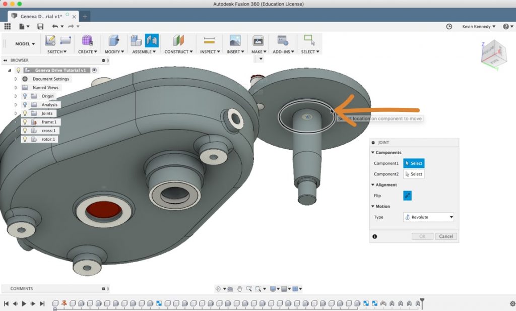
The next step is to add a “joint” to the rotor so we can move it into place with the frame and cross components. If you’re not familiar with the difference between “joints” and “as-built joints” then be sure to check out this video.
Hit the keyboard shortcut letter “J” to call the Joint command. Then, you’ll need to change the motion type to “revolute,” because you’ll want this rotor to spin around a single axis.
Next, look atRe-arranges screen to look at selected object. More the Rotor component from the bottom. This will help you select the correct edge (pictured above). Select the edge of the first extrusion.
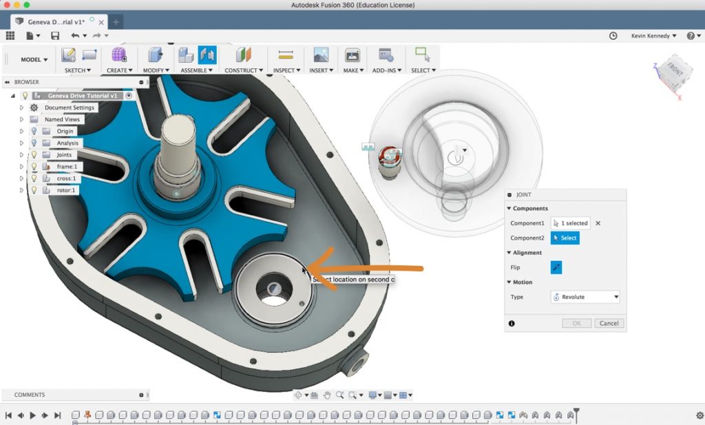
For the second selection, you’ll need to look at the frame from the top. You’ll want to select the corresponding outer edge.
The nice thing about Fusion 360 is that it will give you a nice preview of the animation – so you can confirm that the motion is correct. It will also automatically turn the other components opacity down. If you look at this model from the side view you can make sure that everything is lining up correctly. As long as everything looks good you can click okay in the Joint dialog box.
4. Check the Revolute Joints
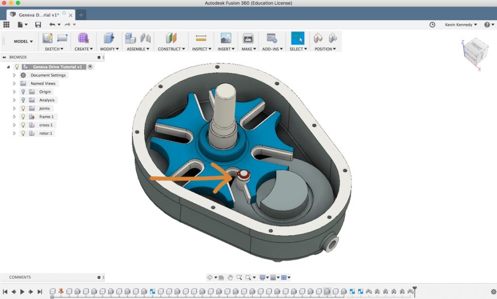
Now you’ll want to click and drag on the rotor. Do the same on the “cross” component. Do they both revolveRevolves a sketch profile or planar face around a selected axis. Select a profile or planar face then select the axis to revolve around. More correctly around their given axis?
At this pointCreates a sketch point. More, they should appear to interfere with each other. This isn’t very realistic and doesn’t make the Geneva Drive work properly, so we’ll have to fix it.
To fix this we’ll have to create a contact set. Hit “revert” in the toolbar to make sure every component is in its normal position.
5. Set Up the Contact Set
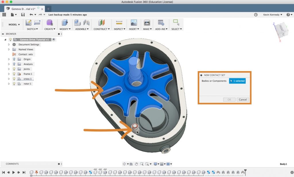
First, you’ll have to select “Enable Contact SetsActivates contact analysis between components in contact sets. Contact sets are managed in the browser. More” from the assemble dropdown list. This tells Fusion that we’re ready to create a contact set, and it enables the option in the assemble dropdown list.
Now, you’ll have to select “new contact set” from the assemble dropdown list. The first thing you’ll have to do is select the “cross” component. Then, for the second component, you’ll need to select the component that will actually come into contact with the first (Cross) component. In this case, it’s the white cylinder component, so you’ll have to select the white cylinder.
6. Check that the Geneva Drive Works!
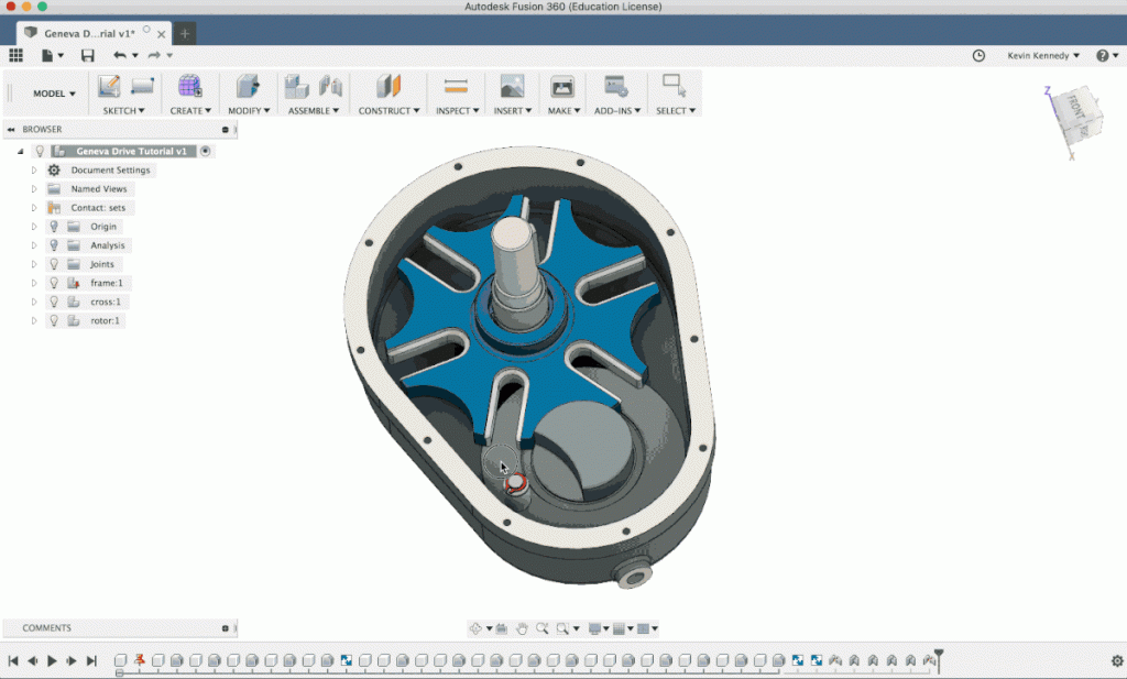
Click “okay” in the dialog box. You can now test the Geneva Drive by manually moving the rotor around. You should see that the two components work together like they’re intended to.
Leave a Reply